
One of the most important techniques every IoT maker must master is ESP32 deep sleep. When you are running your ESP32 from a battery — whether it is a Li-Ion cell, an 18650, or a LiPo pack — the default active mode consumes around 240mA, which will drain even a large battery in hours. By using deep sleep mode, you can reduce current consumption to as low as 10 microamps (μA), extending battery life from hours to months or even years. This tutorial covers everything you need to know about ESP32 deep sleep with practical Arduino code examples.
Why Deep Sleep is Essential for Battery IoT
Consider a typical IoT scenario: you want to measure soil moisture in a farm, monitor a cold storage unit temperature, or track an asset’s GPS location every 5 minutes. In each case, the ESP32 only needs to be active for about 2–3 seconds per cycle to wake up, read a sensor, send data over Wi-Fi, and go back to sleep. The rest of the time — 97% or more — it can be in deep sleep drawing almost zero current.
Here is what makes ESP32 deep sleep remarkable:
- Active mode current: ~240mA (with Wi-Fi transmitting)
- Modem sleep: ~3-20mA
- Light sleep: ~0.8mA
- Deep sleep: ~10-150μA (depending on RTC peripherals enabled)
That is a difference of over 1000x between active and deep sleep. For a 2000mAh 18650 battery, active mode gives you roughly 8 hours, while deep sleep (with 3-second wake cycles every 5 minutes) can stretch that to over 6 months.
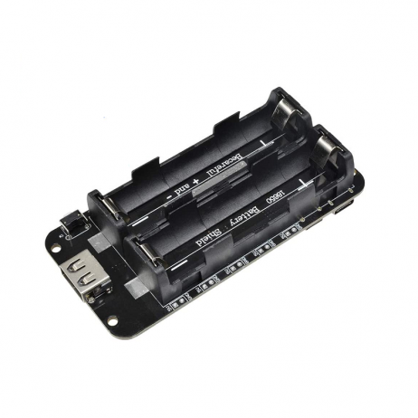
2 x 18650 Lithium Battery Shield for Arduino/ESP32/ESP8266
Power your ESP32 deep sleep project with dual 18650 cells. Includes USB charging, 5V/3.3V output, and switchover protection — perfect for long-term deployments.
ESP32 Sleep Modes Compared
The ESP32 offers five power modes. Understanding each helps you choose the right one for your application:
| Sleep Mode | Current Draw | CPU | Wi-Fi/BT | RAM Retention |
|---|---|---|---|---|
| Active | 240mA | ON | ON | Full |
| Modem Sleep | 3–20mA | ON | Off between beacons | Full |
| Light Sleep | 0.8mA | Paused | OFF | Full |
| Deep Sleep | 10–150μA | OFF | OFF | RTC only |
| Hibernation | 2.5μA | OFF | OFF | None |
For most battery-powered IoT projects, deep sleep is the sweet spot — it retains RTC memory (useful for storing a small amount of data between wake cycles), supports multiple wakeup sources, and achieves near-hibernation power consumption with much more flexibility.
Deep Sleep Wakeup Sources
The ESP32 supports several methods to wake from deep sleep:
- Timer: Wake after a specified number of microseconds. Used for periodic sensor readings.
- External Wakeup (ext0): Wake when a single GPIO pin reaches a defined logic level. Ideal for PIR sensors and magnetic reed switches.
- External Wakeup (ext1): Wake when any/all of multiple GPIO pins are at a defined level.
- Touch: Wake when a capacitive touch pin is touched.
- ULP Co-processor: Ultra Low Power co-processor can run simple tasks and wake the main CPU when a threshold is crossed.
Timer Wakeup: Periodic Sensor Readings
The most common use case for deep sleep is periodic data collection. Your ESP32 wakes up, reads a sensor, transmits data, and goes back to sleep. Here is the complete code:
#include <Arduino.h>
#include <DHT.h>

#define DHTPIN 4
#define DHTTYPE DHT11
#define uS_TO_S_FACTOR 1000000ULL  // Microseconds to seconds
#define SLEEP_TIME_SECONDS 300     // 5 minutes

DHT dht(DHTPIN, DHTTYPE);

// RTC memory persists across deep sleep cycles
RTC_DATA_ATTR int bootCount = 0;

void setup() {
  Serial.begin(115200);
  bootCount++;
  Serial.printf("Boot number: %dn", bootCount);

  // Check wakeup reason
  esp_sleep_wakeup_cause_t wakeup_reason = esp_sleep_get_wakeup_cause();
  if (wakeup_reason == ESP_SLEEP_WAKEUP_TIMER) {
    Serial.println("Wakeup caused by timer");
  }

  dht.begin();
  delay(2000); // DHT needs 2 seconds to stabilise

  float temp = dht.readTemperature();
  float humidity = dht.readHumidity();

  if (!isnan(temp)) {
    Serial.printf("Temperature: %.1f°C | Humidity: %.1f%%n", temp, humidity);
    // Here you would send data via WiFi/MQTT/HTTP
    // sendDataToCloud(temp, humidity);
  }

  // Configure timer wakeup
  esp_sleep_enable_timer_wakeup(SLEEP_TIME_SECONDS * uS_TO_S_FACTOR);
  Serial.println("Going to sleep for 5 minutes...");
  Serial.flush();
  esp_deep_sleep_start();
}

void loop() {
  // Never reached during deep sleep cycles
}
Notice the RTC_DATA_ATTR prefix on bootCount — this is crucial. Variables with this attribute are stored in the RTC slow memory, which persists across deep sleep cycles. Without it, your variable would reset to zero every time the ESP32 wakes up. You can store up to 8KB of data in RTC memory, which is enough for most use cases like keeping a message count, last sensor reading, or connection credentials.
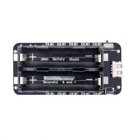
2 x 18650 Lithium Battery Shield V8 for ESP32/ESP8266
This V8 model supports up to 3A output at 5V and 1A at 3.3V via Micro USB — ideal for field-deployed ESP32 deep sleep nodes that need high burst current during Wi-Fi transmission.
External Wakeup: PIR or Touch Sensor
For event-driven applications — such as a doorbell, a security sensor, or a mailbox alert — you want the ESP32 to wake only when something happens. This is where external wakeup excels.
Using ext0 Wakeup with a PIR Sensor
#define PIR_PIN GPIO_NUM_33

void setup() {
  Serial.begin(115200);

  esp_sleep_wakeup_cause_t reason = esp_sleep_get_wakeup_cause();
  if (reason == ESP_SLEEP_WAKEUP_EXT0) {
    Serial.println("Motion detected! Sending alert...");
    // Connect WiFi and send notification
  }

  // Configure GPIO 33 wakeup on HIGH signal
  esp_sleep_enable_ext0_wakeup(PIR_PIN, 1);
  esp_deep_sleep_start();
}

void loop() {}
Important note: only RTC-capable GPIO pins can be used for ext0 wakeup. On most ESP32 boards, GPIO 0, 2, 4, 12–15, 25–27, and 32–39 are RTC-capable. GPIO 34–39 are input-only and work well for external wakeup.
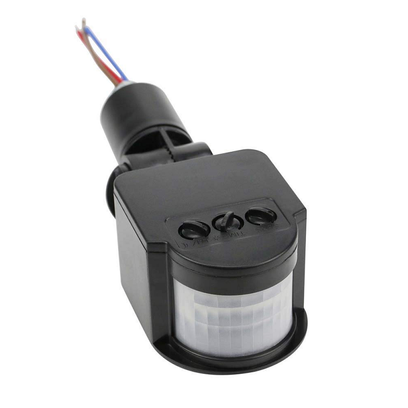
PIR Human Body Motion Sensor Detector
Pair a PIR motion sensor with ESP32 ext0 wakeup for an ultra-low-power security camera or alert system that only activates on motion detection.
Battery Life Calculation
Here is how to calculate expected battery life for a typical deep sleep project. Assume:
- Battery capacity: 4000mAh (two 18650 cells in parallel)
- Active time per cycle: 4 seconds (connect WiFi + send data)
- Active current: 200mA average (Wi-Fi transmission peak is higher)
- Sleep time per cycle: 296 seconds (5 minutes minus 4 sec active)
- Deep sleep current: 20μA = 0.020mA
| Phase | Duration | Current | Charge Used |
|---|---|---|---|
| Active | 4s | 200mA | 0.222mAh |
| Deep Sleep | 296s | 0.020mA | 0.001644mAh |
| Total per 5-min cycle | 0.2237mAh | ||
| Cycles per day (288 cycles) | 64.4mAh/day | ||
| Battery life (4000mAh) | ~62 days | ||
Over two months on two 18650 batteries — that is the power of deep sleep done right. You can push this even further by extending the sleep interval to 15 or 30 minutes for non-critical monitoring applications.
Real-World Project: Battery-Powered Weather Station
Here is a complete architecture for a solar-powered, battery-backed weather station that runs indefinitely:
- ESP32 + BME280 (temperature, humidity, pressure) + battery shield
- Wake every 15 minutes, read sensors (2 seconds), connect to Wi-Fi (3 seconds), POST data to API (1 second), sleep again (6 seconds active per cycle)
- With 4x 18650 batteries (8000mAh) and a small 5W solar panel, this system is effectively self-sustaining year-round across India
The key optimisation is WiFi fast connect: store the BSSID and channel in RTC memory after the first connection so subsequent reconnections take under 1 second instead of the usual 4–5 seconds. This alone can double your battery life.
RTC_DATA_ATTR uint8_t bssid[6];
RTC_DATA_ATTR uint8_t channel;

// After first connection, save:
memcpy(bssid, WiFi.BSSID(), 6);
channel = WiFi.channel();

// On subsequent boots, use:
WiFi.begin(ssid, password, channel, bssid, true);
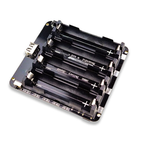
4 x 18650 Lithium Battery Shield V8/V9 for ESP32/ESP8266
Quad-cell 18650 battery shield with on/off button and dual USB output. Provides up to 8000mAh+ capacity for truly long-term field deployments of battery-powered ESP32 nodes.
Frequently Asked Questions
Does GPIO state get preserved during ESP32 deep sleep?
No. When ESP32 enters deep sleep, GPIO pins revert to their default state (input mode, floating). If you are driving an LED or a relay, it will turn off during sleep. To hold a GPIO high during sleep, use the RTC GPIO hold function: gpio_hold_en(GPIO_NUM_X) before entering sleep, and gpio_hold_dis(GPIO_NUM_X) after waking up.
Why does my ESP32 use more than 10μA in deep sleep?
Several factors increase deep sleep current beyond the minimum: (1) the onboard LED or power indicator on your development board; (2) USB-to-UART chip (CP2102/CH340) which often draws 1–5mA even when not in use; (3) pull-up resistors on I2C lines; (4) voltage regulator quiescent current. For truly minimal deep sleep current, use a bare ESP32 module (not a development board) in your final product design.
Can I use Arduino delay() instead of deep sleep?
Technically yes, but it is extremely inefficient. delay() keeps the CPU running and burning ~50mA. Deep sleep at 20μA is 2500 times more efficient for the same waiting period. For any battery-powered project with a wait time over 10 seconds, always use deep sleep.
How do I debug ESP32 deep sleep issues?
Add boot count tracking with RTC_DATA_ATTR to confirm your ESP32 is waking up. Use a USB-to-Serial adapter and monitor the Serial output at the start of setup(). Check esp_sleep_get_wakeup_cause() to confirm the correct wakeup source. If the board is not waking from timer, ensure you are calling esp_sleep_enable_timer_wakeup() before esp_deep_sleep_start().
What is the minimum deep sleep duration for ESP32?
The minimum RTC timer wakeup resolution is approximately 5 microseconds, though in practice anything under 1 millisecond may be unreliable. For most applications, a minimum sleep of 100ms is recommended. There is no maximum — the RTC timer is 48-bit and can theoretically count up to 1.5 years.
Build Your Battery-Powered IoT Project
Get ESP32 boards, battery shields, sensors, and all IoT components delivered across India. Zbotic stocks everything you need to build long-lasting, power-efficient IoT devices.


Add comment