
The ESP32 DAC (Digital-to-Analog Converter) is a powerful built-in feature that sets the ESP32 apart from most other microcontrollers including the Arduino. While the Arduino can only produce PWM signals that approximate analog output, the ESP32 has two true 8-bit DAC channels that generate genuine analog voltage levels — enabling you to create smooth sine waves, audio output, signal generators, and precise voltage references without any external hardware. This tutorial covers everything you need to know to use the ESP32 DAC effectively.
What is a DAC and How Does It Work?
A Digital-to-Analog Converter (DAC) translates digital numeric values into corresponding analog voltage levels. Unlike PWM (Pulse Width Modulation), which rapidly switches between HIGH and LOW to simulate an average voltage, a true DAC outputs a smooth, continuous voltage at any point between its minimum and maximum range.
This distinction matters enormously for certain applications:
- Audio: PWM audio requires heavy filtering and still sounds harsh. DAC audio is smooth and clean.
- Signal generation: PWM approximations of sine waves have significant harmonic distortion. DAC sine waves are genuine analog signals.
- Voltage reference: PWM voltage references require capacitors to smooth the output. DAC references are stable instantaneously.
- Sensor simulation: Testing an ADC circuit by generating a known analog voltage is simple with a DAC, impractical with PWM.
The ESP32 includes two independent 8-bit DAC channels, giving 256 discrete voltage levels from 0V to VCC (nominally 3.3V on most development boards).
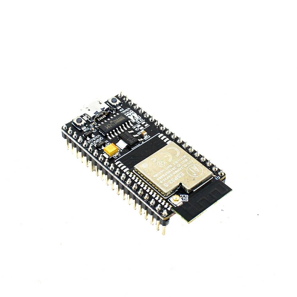
Ai Thinker NodeMCU-32S ESP32 Development Board
The NodeMCU-32S exposes both DAC-capable pins (GPIO 25 and GPIO 26) on accessible breakout headers, making it the ideal board for DAC experiments and audio projects.
ESP32 DAC Specifications
Here are the complete specifications of the ESP32’s built-in DAC:
| Parameter | DAC1 (GPIO 25) | DAC2 (GPIO 26) |
|---|---|---|
| Resolution | 8-bit (256 levels) | |
| Voltage range | 0V to VDD3P3 (~3.3V) | |
| LSB voltage step | ~12.9mV | |
| Max output current | ~1mA (use buffer/op-amp for loads) | |
| Max software update rate | ~10,000 samples/sec (software) | |
| DMA-driven max rate | Up to ~1MHz (8-bit audio: ~44.1kHz) | |
| Built-in cosine generator | Yes (hardware, configurable freq.) | |
| Arduino pin numbers | 25 | 26 |
Note that the DAC output cannot drive low-impedance loads directly. For driving speakers, you need an audio amplifier. For driving ADC inputs on another board, direct connection is fine. The ESP32 DAC output has an output impedance of about 3kΩ, meaning it will droop significantly under any real load.
Basic DAC Output with Arduino Code
Setting a DAC output is as simple as calling dacWrite():
#define DAC1 25  // GPIO 25
#define DAC2 26  // GPIO 26

void setup() {
  Serial.begin(115200);
}

void loop() {
  // Sweep DAC1 from 0V to 3.3V
  for (int i = 0; i <= 255; i++) {
    dacWrite(DAC1, i);
    float voltage = (i / 255.0) * 3.3;
    Serial.printf("DAC value: %d | Voltage: %.2fVn", i, voltage);
    delay(20);
  }

  // Sweep back down
  for (int i = 255; i >= 0; i--) {
    dacWrite(DAC1, i);
    delay(20);
  }
}
Connect a voltmeter to GPIO 25 and GND to verify the output is sweeping from 0V to approximately 3.3V. You can also connect an LED through a 330Ω resistor — it will smoothly fade in and out, unlike PWM which can appear to flicker.
Fixed Voltage Reference
To output a precise voltage (within the 8-bit resolution limit):
// Output 1.65V (midpoint, DAC value 128)
void setVoltage(int dacPin, float voltage) {
  int dacValue = (int)((voltage / 3.3) * 255);
  dacValue = constrain(dacValue, 0, 255);
  dacWrite(dacPin, dacValue);
  Serial.printf("Set DAC to value %d (%.3fV actual)n", dacValue, dacValue * 3.3 / 255.0);
}

void setup() {
  Serial.begin(115200);
  setVoltage(DAC1, 1.65);  // Output 1.65V on GPIO 25
  setVoltage(DAC2, 0.825); // Output 0.825V on GPIO 26
}
Waveform Generation: Sine, Triangle, Sawtooth
The ESP32 DAC really shines when generating periodic waveforms. Here is code that generates a sine wave at a specified frequency:
#include <math.h>

#define DAC1 25
#define SAMPLE_RATE 10000  // 10kHz sample rate
#define FREQ_HZ 440        // Generate 440Hz (middle A)
#define SAMPLES_PER_CYCLE (SAMPLE_RATE / FREQ_HZ)

// Pre-calculate sine table for speed
uint8_t sineTable[SAMPLES_PER_CYCLE];

void setup() {
  Serial.begin(115200);

  // Build sine lookup table
  for (int i = 0; i < SAMPLES_PER_CYCLE; i++) {
    float angle = 2.0 * M_PI * i / SAMPLES_PER_CYCLE;
    sineTable[i] = (uint8_t)(128 + 127 * sin(angle));
  }
  Serial.printf("Generating %dHz sine wave at %d spsn", FREQ_HZ, SAMPLE_RATE);
}

void loop() {
  for (int i = 0; i < SAMPLES_PER_CYCLE; i++) {
    dacWrite(DAC1, sineTable[i]);
    delayMicroseconds(1000000 / SAMPLE_RATE); // 100μs for 10kHz
  }
}
This generates a 440Hz sine wave (musical note A) on GPIO 25. Connect an oscilloscope or a simple audio amplifier circuit to observe the waveform.
Triangle Wave
void generateTriangleWave(int dacPin, int frequency) {
  int periodUs = 1000000 / frequency;
  int halfPeriodUs = periodUs / 2;
  int stepUs = halfPeriodUs / 255;

  // Rising edge
  for (int i = 0; i <= 255; i++) {
    dacWrite(dacPin, i);
    delayMicroseconds(stepUs);
  }
  // Falling edge
  for (int i = 255; i >= 0; i--) {
    dacWrite(dacPin, i);
    delayMicroseconds(stepUs);
  }
}
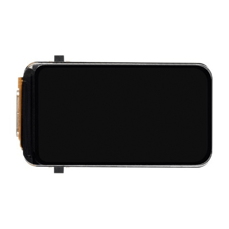
Waveshare ESP32-S3 1.47inch LCD Display Development Board
Build a mini oscilloscope or waveform viewer by generating signals with DAC and displaying the waveform on this compact 172×320 colour LCD display — a great educational project.
Audio Output with ESP32 DAC
The ESP32 DAC is capable of basic audio playback. For 8-bit mono audio at 8000Hz sample rate (telephony quality), the software approach works well. For better quality (16-bit stereo CD quality), use I2S with an external DAC chip. Here is how to play a simple tone through the DAC:
#include <Arduino.h>

#define DAC_PIN DAC1  // GPIO 25
#define SAMPLE_RATE 8000

// Simple 8-bit sine wave audio sample (440Hz, 1 cycle)
const uint8_t sine440[] = {
  128,147,166,185,203,219,234,245,253,255,
  253,248,240,229,216,201,185,168,151,135,
  119,104,90,77,66,56,48,43,40,40,
  42,47,55,64,75,88,102,116,131,146
};
const int sine440Len = sizeof(sine440);

void playTone(int durationMs) {
  unsigned long start = millis();
  int idx = 0;
  while (millis() - start < durationMs) {
    dacWrite(DAC_PIN, sine440[idx]);
    idx = (idx + 1) % sine440Len;
    delayMicroseconds(1000000 / SAMPLE_RATE);
  }
  dacWrite(DAC_PIN, 128); // Return to midpoint (silence)
}

void setup() {
  playTone(500); // Play 440Hz for 0.5 seconds
  delay(200);
  playTone(500);
}

void loop() {}
To drive a small speaker, you MUST use an audio amplifier between the DAC and the speaker. The PAM8403 (3W stereo) or LM386 amplifier modules are popular and affordable in India. Connect DAC output → amplifier input → 8Ω speaker for audible audio.
Playing WAV Files from SPIFFS
The ESP32 can store WAV files in its built-in SPIFFS filesystem and stream them through the DAC. Libraries like the ESP8266Audio library (which also supports ESP32) handle the heavy lifting. This enables voice prompts, alarms, and notification sounds in your IoT projects without any external storage.
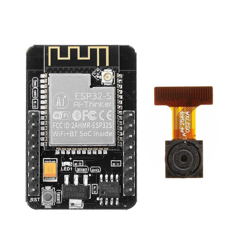
Ai Thinker ESP32-CAM Development Board with Camera
The ESP32-CAM includes the same DAC outputs. Build a talking security camera that plays audio alerts through the DAC when motion is detected — combine video, AI, and audio in one board.
Using the Built-In Cosine Wave Generator
The ESP32 has a hardware cosine (CW) generator built into the DAC subsystem. This can generate frequencies from a few Hz up to several MHz without any CPU involvement — true hardware signal generation. Access it via the ESP-IDF API:
#include <driver/dac.h>

void setup() {
  Serial.begin(115200);

  // Enable DAC1 cosine wave generator
  dac_cw_config_t cw_config = {
    .en_ch = DAC_CHANNEL_1,     // GPIO 25
    .scale = DAC_CW_SCALE_1,    // Full scale output
    .phase = DAC_CW_PHASE_0,    // 0 degree phase
    .freq = 1000,               // 1kHz
    .offset = 0                 // No DC offset
  };

  dac_cw_generator_config(&cw_config);
  dac_cw_generator_enable();
  dac_output_enable(DAC_CHANNEL_1);

  Serial.println("Hardware 1kHz cosine wave active on GPIO 25");
  Serial.println("CPU is completely free for other tasks!");
}

void loop() {
  // CPU is free — do your IoT work here
  // The DAC is generating the cosine wave in hardware
  delay(1000);
}
The hardware cosine generator is a game changer for signal generation applications. The CPU does zero work after configuration, leaving all processing power available for Wi-Fi communication, data processing, and display updates.
Practical Applications
1. Audio Doorbell with Custom Chimes
Store 3–4 different chime WAV files in SPIFFS. Play a random chime through the DAC when the doorbell button is pressed. Combine with ESP32 Wi-Fi to send a simultaneous push notification. Total BOM cost under ₹500 including the ESP32 and speaker.
2. Function Generator
Build a handheld function generator that outputs sine, square, triangle, and sawtooth waves from 1Hz to 10kHz. Use a rotary encoder to adjust frequency, display frequency on a small OLED screen. Connect output to a BNC connector via a simple op-amp buffer. Useful for electronics lab work and debugging analog circuits.
3. Analog Sensor Simulator
When developing code for a system that reads an analog sensor, simulate the sensor output using the DAC. Generate controlled voltages to test your ADC reading code and calibration constants without needing the physical sensor present — saves time during development and debugging.
4. Ultrasonic Signal Generator
Generate 25–40kHz ultrasonic signals for custom transducer testing or ultrasonic distance measurement experiments. The hardware cosine generator can reach these frequencies easily. Combine with an ultrasonic receiver to measure time-of-flight.

25kHz Ultrasonic Sensor Receiver T25 16mm
Pair with the ESP32 DAC-driven ultrasonic transmitter for custom time-of-flight distance measurement experiments. The 25kHz frequency is within the ESP32 hardware cosine generator’s range.
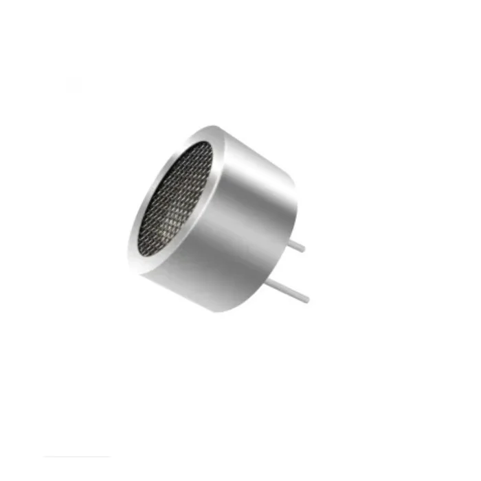
25kHz Ultrasonic Sensor Transmitter T25 16mm
Drive this 25kHz ultrasonic transmitter directly from the ESP32 DAC hardware cosine generator for precise frequency-controlled ultrasonic sensing and distance measurement projects.
Frequently Asked Questions
Does the ESP32-S2 or ESP32-S3 have a DAC?
The ESP32-S2 has two DAC channels (same as original ESP32, on GPIO 17 and GPIO 18). The ESP32-S3 does NOT have a built-in DAC — you must use I2S with an external DAC chip (like PCM5102A) for audio output. The ESP32-C3 and C6 also lack built-in DAC. If your project requires DAC, use the original ESP32 or ESP32-S2.
What is the maximum audio quality achievable with ESP32 DAC?
The built-in DAC is 8-bit, limiting dynamic range to ~48dB (versus 96dB for 16-bit CD audio). Sample rate can reach up to ~44.1kHz using DMA-driven I2S DAC mode. The result is roughly telephone-quality audio — perfectly adequate for voice prompts, alarms, and notification sounds, but not for music playback. For music, use I2S with a PCM5102A or MAX98357A external DAC.
Can I use both DAC channels simultaneously?
Yes. Both DAC1 (GPIO 25) and DAC2 (GPIO 26) operate completely independently. You can output different voltages, different waveforms, or even stereo audio on both channels simultaneously. The hardware cosine generator can also be configured independently on each channel with different frequencies and phase offsets.
Why does my DAC output have a DC offset or not reach 0V?
The ESP32 DAC has a known non-linearity at both extremes (values 0–10 and 245–255). The minimum output is approximately 0.05V rather than true 0V. For precision applications, calibrate by measuring actual output at known DAC values and applying a correction factor. Also, any load resistance connected to the output will cause voltage droop due to the DAC’s ~3kΩ output impedance.
How do I stop a running DAC output?
Call dacWrite(DAC1, 128) to set the output to mid-supply (1.65V, which is the “zero” for AC-coupled audio systems) or dacWrite(DAC1, 0) for 0V. To completely disable the DAC and reclaim GPIO 25/26 for other use, call dac_output_disable(DAC_CHANNEL_1) from the ESP-IDF DAC driver.
Get Your ESP32 and Start Building
Zbotic stocks a full range of ESP32 development boards, audio components, sensors, and accessories — all available with fast delivery across India. Start your DAC project today.


Add comment