
Understanding an ebike wiring diagram controller battery system is the single most important skill for anyone building or repairing a DIY electric bicycle in India. A wrong connection can destroy a ₹5,000 controller in seconds, or worse, cause a lithium battery to catch fire. This guide walks you through every wire, connector and terminal you will encounter, from the battery pack all the way to the wheel motor, with practical tips suited to Indian riding conditions.
Anatomy of an E-Bike Electrical System
Every e-bike electrical system has five core blocks that must work together: the battery pack, the Battery Management System (BMS), the controller (ESC), the display/speedometer, and the motor. Add-ons like throttle, brake sensors, lights and horn connect to the controller as auxiliary inputs.
The power flow is simple: Battery → BMS → Controller → Motor. The BMS protects the lithium cells from over-discharge, over-charge and short circuits. The controller converts DC battery power into the three-phase AC the brushless motor needs. The display lets you read speed, battery level and select assist mode, while sending enable/disable signals to the controller.
Wire gauges matter enormously. The high-current path (battery to controller to motor phases) uses 10–14 AWG silicone wire. Signal wires — hall sensor, throttle, brake — are thin 22–26 AWG. Using undersized wire on power runs causes voltage drop, overheating and fires. Always match the wire cross-section to the continuous current, not peak.
Battery Wiring: Pack, BMS and Output
A typical Indian DIY e-bike uses a 36 V or 48 V lithium-ion pack assembled from 18650 or 21700 cells. The BMS has three sets of wires:
- B– (battery negative): connects to the negative terminal of the cell pack.
- C– (charge negative): connects to the charger port negative.
- P– (discharge negative): connects to the controller negative. Never short B– to P–.
- B+ / P+: common positive from cell pack to both charger and controller.
- Balance leads: thin wires tapped between each cell group, connect to BMS balance port.
The discharge output wires (B+ and P–) run to an XT60 or Anderson connector. The main switch sits on the positive rail before the controller. Always add a slow-blow fuse rated at 1.5× your controller’s max current on the positive wire within 15 cm of the battery terminal.
For a 48 V 20 Ah pack on a 500 W motor drawing up to 15 A continuous, use a 25 A fuse and 12 AWG wire minimum for the battery-to-controller run.

Ebike 500W 24V DC 2500 RPM Motor MY1020
Popular chain-drive motor for scooter, go-kart and minibike e-ATV builds. Runs on 24 V DC and includes mounting bracket. A great starting point for first-time e-bike builders.
Controller Connections Explained
The controller is the brain of the system. It accepts DC from the battery and outputs three-phase AC to the motor. Every modern BLDC e-bike controller has a standardized set of connectors. Here is what each one does:
- Battery positive (red, thick): main power in from B+.
- Battery negative (black, thick): main ground from P–.
- Phase wires A/B/C (usually yellow/green/blue, thick): three-phase output to motor stator.
- Hall sensor connector (5-wire JST/SM): +5 V, GND, Hall A, Hall B, Hall C — reads rotor position.
- Throttle (3-wire JST): +5 V, GND, signal (0.8–4.2 V range).
- Brake (2-wire): normally-closed switch; opening it cuts motor power instantly.
- Display/communication (usually 5-wire): power for display, TX/RX or single-wire UART.
- Key switch: two-wire ignition input. Bridging it enables the controller.
- Speed sensor output: feeds display with wheel rotation pulses.
- Lights (optional): switched 6 V or 12 V output for headlight/taillight.
Phase wire colour-to-motor terminal matching is critical. Most controllers ship pre-matched, but if you swap a controller, test all six combinations until the motor runs smoothly and quietly. Mismatched phases produce violent jerking or no rotation at all.
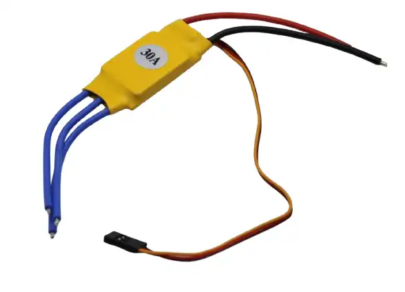
30A BLDC ESC Brushless Electronic Speed Controller
30 A continuous BLDC ESC suitable for small e-bike, e-scooter and robotics applications. Features smooth acceleration profile and braking support. Compact and easy to wire.
Display and Throttle Wiring
The display (often called the speedometer or LCD panel) connects to the controller via a 5-pin or 8-pin waterproof connector. Common protocols are KT-LCD3/LCD8 for KT controllers and SW-900 for generic Chinese controllers. The display powers up from the controller’s internal 5 V rail — never apply external 12 V to the display connector.
Throttle wiring is three-wire: red (+5 V), black (GND) and green/white (signal). The hall-effect thumb or twist throttle outputs 0.8 V at rest and 4.2 V at full. Voltages outside this range trigger a throttle fault on most controllers. Always check throttle idle voltage with a multimeter before first ride — a throttle stuck at 1.5 V at rest will cause unexpected acceleration.
Brake sensors are the simplest wires on the bike. The hydraulic brake lever has a normally-closed (NC) magnetic switch. When you pull the lever, the circuit opens, and the controller kills motor output within milliseconds. Use the NC type, not NO (normally-open). Wiring NO brakes backwards will keep the motor off permanently.
Motor Phase Wires and Hall Sensors
Brushless hub motors have six wires exiting through the axle: three thick phase wires and five thin hall sensor wires. The phase wires carry high current (10–30 A) and must have robust, waterproofed connectors — use MR60 or XT30U for the phase connections, not bare crimp pins.
Hall sensor wires (+5 V, GND, HA, HB, HC) are low-current signal lines but extremely sensitive to noise. Keep them away from the phase wires and route them separately. A damaged or loose hall wire causes stuttering, loss of sync and can overheat the motor driver FETs in the controller.
If you are running a sensorless controller (common in budget builds), the motor starts with back-EMF detection instead of hall sensors. Sensorless motors struggle at very low speed and under high load from standstill — expect some cogging or jerk when moving off. Sensored controllers eliminate this.

Waveshare DDSM115 Direct Drive Hub Motor
Low-speed, high-torque direct drive hub motor with integrated servo driver. Ideal for e-bike and UGV wheel drive applications requiring precise speed control and low noise operation.
Wiring Safety Tips for India
India’s conditions demand extra attention to wiring quality. Monsoon humidity, potholed roads and extreme summer heat are the three biggest enemies of e-bike wiring.
- Use silicone-insulated wire: PVC insulation cracks below -10 °C and melts at 70 °C. Silicone handles -60 °C to 200 °C and is flexible enough to survive vibration.
- Waterproof all connectors: apply liquid electrical tape or self-amalgamating tape over every SM/JST connector exposed outside the frame. Waterproofing the controller box with silicone sealant around the wire entry points is essential before the first monsoon.
- Strain relief at every entry point: zip-tie wires to the frame before they enter controllers and batteries. Vibration breaks solder joints and pulls connector pins out over time.
- Label everything before assembly: use heat-shrink labels or permanent marker. When you need to debug at night by the roadside, you will thank yourself.
- Never bypass the BMS for more power: this is the most common cause of lithium fires in Indian e-bike builds.
Common Wiring Mistakes and Fixes
These are the errors seen most often in Indian DIY e-bike communities:
- Reversing B– and P–: bypasses BMS protection and can cause immediate cell damage. Always check polarity with a multimeter before the first power-on.
- Undersized main fuse: a 15 A fuse on a 48 V 750 W system will blow repeatedly. Calculate fuse rating as (Watts ÷ Volts) × 1.5 minimum.
- Sharing GND with signal and power wires: causes controller brownouts and display glitches. Use a star grounding topology — all grounds meet at one point near the battery negative.
- Loose XT60 connector: vibration loosens the crimp. Re-solder all high-current connections, do not rely on crimps alone.
- Phase wires touching each other: causes controller FET failure immediately at power-on. Insulate each phase wire end before connecting one at a time.
- Hall sensor wire routed too close to motor phases: induces noise that scrambles the sensor signal. Use separate, shielded conduit for signal wires.

Waveshare Compact UGV Suspension for DDSM115
All-metal suspension frame with high-strength springs, 7.5 kg load capacity, designed for DDSM115 hub motor. Perfect for building compact electric vehicle platforms with proper shock absorption.
Frequently Asked Questions
- Q: What is the correct wire colour order for e-bike phase wires?
- A: There is no universal standard. KT controllers typically use yellow, green and blue. However, always verify by testing combinations, not by colour alone. Matching colours between controller and motor does not guarantee correct phasing.
- Q: Can I use a car fuse holder for e-bike battery wiring?
- A: ATC/ATO blade fuse holders rated for 30 A are fine for e-bikes up to 750 W on 48 V. For higher power, use a ANL fuse holder with a bolt-down fuse, which handles vibration better.
- Q: Why does my display show error E06 (or similar)?
- A: E06 on most KT/generic controllers means throttle signal fault — the voltage at rest is out of the 0.8–1.2 V window. Check for a loose pin in the throttle connector or a failed hall-effect sensor inside the throttle.
- Q: Do I need a shunt resistor between battery and controller?
- A: Most controllers have an internal current sense shunt. An external shunt is only needed if you are adding a separate battery monitor or coulomb counter for accurate State of Charge tracking.
- Q: How do I waterproof XT60 connectors for monsoon riding?
- A: Slide a short section of heat-shrink over one half before mating them, and apply self-amalgamating tape over the joint. Do not use regular electrical tape — it unravels with heat and vibration.
Build Your E-Bike with Quality Components
Zbotic stocks BLDC motors, ESCs, gear motors and e-bike mechanical parts for DIY builders across India. Get the right components for your build shipped fast.


Add comment