
Building a robot that walks on two legs is one of the most challenging and rewarding problems in robotics. The secret to stable biped walking in humanoid robots lies in a concept called the Zero Moment Point (ZMP) — a mathematical criterion that determines whether a walking robot will fall over or remain balanced. This guide demystifies ZMP theory and shows you how to implement it practically on a servo-based humanoid using Arduino or ESP32.
Why Biped Locomotion Is Hard
A table with four legs is passively stable — it stands without any active control. A biped robot with two legs is inherently unstable, like an inverted pendulum. At every instant, it must actively compute where to place its feet and how to move its body’s centre of mass (CoM) to avoid falling.
Wheels solve mobility perfectly for flat surfaces, but legs confer enormous advantages: they can step over obstacles, climb stairs, navigate uneven terrain, and operate in environments built for humans. That’s why Boston Dynamics, ASIMO, and India’s own DRDO humanoids all use legs despite their engineering complexity.
For hobby builders, a 17–21 servo biped is achievable for under ₹15,000 and teaches more control theory than any other robotics project. The challenge is getting stable, repeatable walking — and ZMP is the theoretical foundation that makes it possible.
What Is Zero Moment Point (ZMP)?
The Zero Moment Point was formulated by Miomir Vukobratović in 1972 and remains the dominant stability criterion for humanoid walking today. The concept: if a robot’s foot is on the ground, there is a point within the support polygon (the foot’s contact area) where the net ground reaction moment is zero. This point is called the ZMP.
The stability rule is simple:
The robot is stable if and only if the ZMP lies within the support polygon (the convex hull of all foot contact points).
When the ZMP moves to the edge of the support polygon, the robot is on the verge of tipping. When it moves outside, the robot falls. By designing gaits that keep the ZMP well inside the foot contact area at all times, you guarantee stable walking without needing real-time balance recovery.
This approach — called ZMP-based pre-planned gait — is what small hobby humanoids (and early ASIMO versions) use. More sophisticated robots (Boston Dynamics Atlas) use dynamic whole-body control, but ZMP pre-planning is the right starting point for hobby builders.
ZMP Mathematics — Simplified
For a simplified planar (2D) analysis of a walking robot, the ZMP x-coordinate is:
ZMP_x = (m * g * x_com - m * x_com_ddot * z_com) / (m * g - m * z_com_ddot)

Where:
  x_com     = horizontal position of Centre of Mass
  z_com     = height of Centre of Mass above ground
  x_com_ddot = horizontal acceleration of CoM
  z_com_ddot = vertical acceleration of CoM (≈0 for level walking)
  g         = 9.81 m/s²
For constant-height walking (z_com = constant, z_com_ddot = 0), this simplifies dramatically to the Linear Inverted Pendulum Model (LIPM):
ZMP_x = x_com - (z_com / g) * x_com_ddotThis is the core equation. By controlling x_com_ddot (how fast the CoM accelerates horizontally) and maintaining constant z_com, you can pre-compute a CoM trajectory that keeps ZMP_x within the foot boundaries for every step.
In practice for a hobby robot: the hip joint horizontal motion defines x_com (approximate the robot as a point mass at the hip). Keep the hip height constant during the walking cycle. Plan hip lateral motion so the ZMP stays centred over the support foot during single-leg stance phases.
Hardware Requirements for a Biped Robot
A capable hobby biped needs at minimum 10 DOF (degrees of freedom) for walking. Full-featured humanoids use 17–21 DOF:
- Each leg: hip roll (lateral lean) + hip pitch (forward/backward) + knee pitch + ankle pitch + ankle roll = 5 DOF × 2 = 10 DOF
- Each arm: shoulder + elbow + wrist = 3 DOF × 2 = 6 DOF (for arm-swinging balance)
- Head: pan + tilt = 2 DOF
- Waist: 1 DOF (optional)
For each DOF you need one servo motor. Ankle and knee joints see the most load — use metal-gear MG996R or digital MG90S servos there. Hip and waist joints use high-torque digital servos (minimum 3 kg-cm). Head and arm joints can use lightweight SG90.
Power: all servos running simultaneously can draw 10–15 A peak. Use a 2S LiPo (7.4 V, 3000+ mAh) with a 5–7.4 V voltage regulator or servo-specific BEC. Do NOT power servos from Arduino’s 5V pin — it cannot supply more than 500 mA and will reset under load.
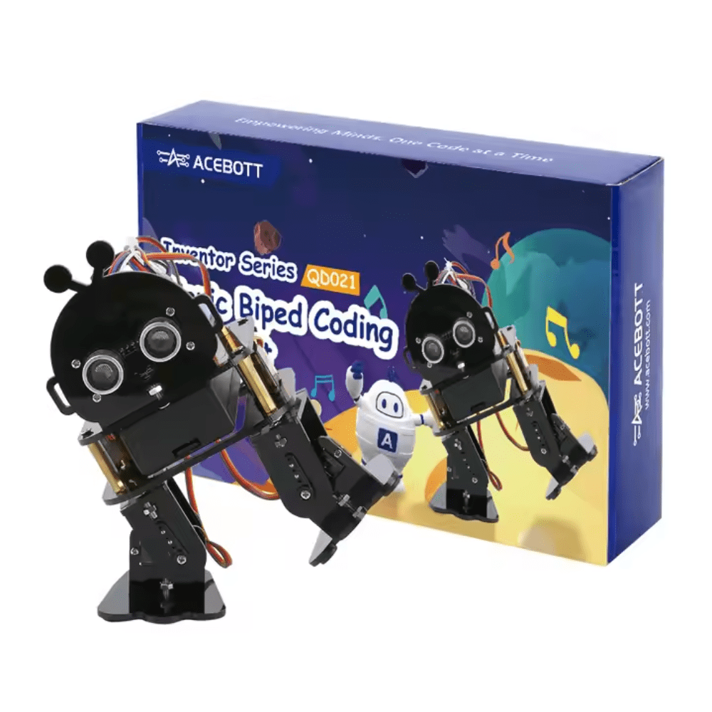
ACEBOTT Biped Robot Kit – QD021
Complete multi-servo biped humanoid robot kit with ESP32 — includes all servos, frame, and controller for ZMP walking experiments.
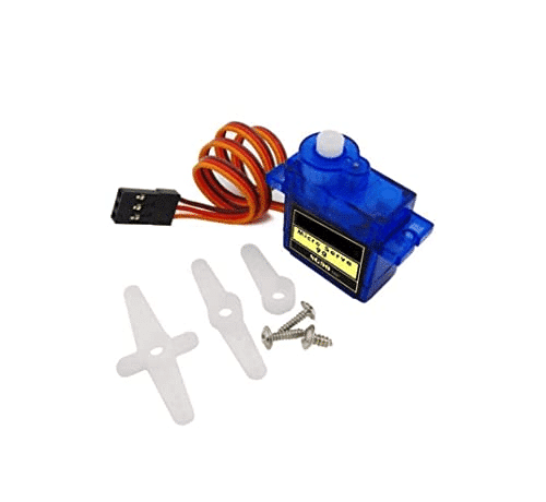
TowerPro SG90 180 Degree Rotation Servo Motor
Lightweight 9g servo suitable for head, arm, and low-load joints in biped humanoid robot builds.
Gait Design and Trajectory Planning
A basic bipedal walk cycle has four phases per step:
- Double Support (DS): Both feet on ground. Robot shifts weight over the stance foot (ZMP moves from centre to stance foot).
- Single Support (SS) — Right foot swing: Left foot only on ground. Right foot swings forward. ZMP must stay over left foot.
- Double Support (DS): Right foot lands. Both feet on ground. Weight shifts to right foot.
- Single Support (SS) — Left foot swing: Right foot only. Left foot swings forward. Repeat.
For pre-planned gait, define servo trajectories as arrays of (joint_angle, time_ms) pairs. Key parameters:
- Step width: Distance between feet laterally. Wider = more stable, but looks unnatural and is slower. Start with 15–20 cm.
- Step length: Forward distance per step. Keep short (3–5 cm for small robots) until walking is stable, then increase.
- Step period: Time for one complete step. Slower = more stable (easier for servos to follow trajectories). Start at 1.5–2 s per step, reduce toward 0.8 s as performance improves.
- Swing height: How high the foot lifts during swing. Too high is slow; too low risks dragging. 1–3 cm typical.
The lateral weight shift (hip roll) is the most critical variable. Before the swing phase, the robot must lean over the stance foot enough that the ZMP is firmly within the foot’s contact area. For a robot with 10 cm × 5 cm feet, keep the ZMP at least 1 cm from each edge — giving you ±3 cm tolerance in ZMP_x and ±1.5 cm in ZMP_y.
IMU Feedback for Balance Correction
Pre-planned ZMP gaits work on perfectly flat surfaces. Real floors have bumps, slopes, and surface variation. An IMU (Inertial Measurement Unit like the MPU-6050) adds a feedback layer that corrects for unexpected tilt.
The correction strategy is a simple tilt-based ankle controller:
roll_error  = target_roll  - imu.getRoll();   // lateral tilt
pitch_error = target_pitch - imu.getPitch();  // forward/backward tilt

ankle_roll_correction  = Kp_roll  * roll_error;
ankle_pitch_correction = Kp_pitch * pitch_error;

set_servo(LEFT_ANKLE_ROLL,  base_angle + ankle_roll_correction);
set_servo(RIGHT_ANKLE_ROLL, base_angle - ankle_roll_correction);
This runs at 50–100 Hz on the Arduino, overlaid on top of the slower (10–20 Hz) gait trajectory execution. When the robot starts to tilt right unexpectedly, the left ankle immediately compensates to push the CoM back left. This dramatically improves walking stability on uneven surfaces without requiring a full ZMP replanning loop.
Use a complementary filter (not just the accelerometer) to get stable roll/pitch angles from the IMU: angle = 0.98 * (angle + gyro * dt) + 0.02 * accel_angle. The gyroscope tracks fast movements; the accelerometer corrects long-term drift. A Madgwick or Mahony filter is even better but more complex to implement.
Implementation on Arduino and ESP32
For a 17-servo biped, use a dedicated servo driver board (PCA9685 I2C, 16 channels) rather than direct Arduino pins. The PCA9685 handles PWM generation for 16 servos via I2C, leaving Arduino GPIO free for sensors and control. You’ll need two boards for 17+ servos.
Software architecture recommendation:
- Task 1 (every 10 ms): Read IMU, compute roll/pitch corrections.
- Task 2 (every 50 ms): Step through gait trajectory table, compute next servo angles.
- Task 3 (every 10 ms): Apply correction to base gait angles, write to PCA9685.
On ESP32, use FreeRTOS tasks pinned to core 0 (control) and core 1 (communication/UI) for clean separation. On Arduino Mega, use a timer interrupt for Task 1 and the main loop for Tasks 2–3.
Store gait tables in PROGMEM (Arduino) or flash (ESP32) to save RAM. A full 17-joint gait table for one step cycle at 10ms resolution requires 17 joints × 200 frames × 2 bytes = 6,800 bytes — fits in Arduino Mega’s 8 KB SRAM, but tightly. ESP32 with 520 KB RAM handles multiple gait patterns easily.
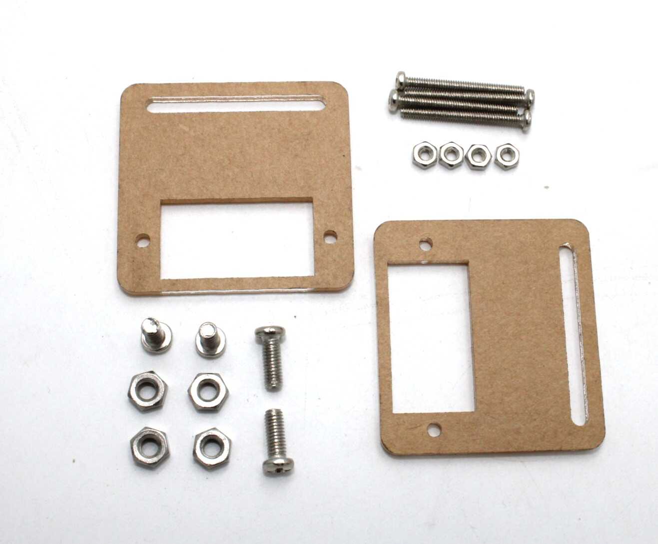
Servo Mount Holder Bracket For SG90/MG90 (Pack of 2)
Essential servo brackets for structurally sound biped robot joint assemblies — prevents servo case stress and misalignment.
Common Problems and Solutions
- Robot falls sideways immediately: Lateral weight shift is insufficient. Increase hip roll angle before entering single-support phase. The rule: the robot’s CoM must be directly above the stance foot before lifting the swing foot.
- Robot walks but curves left/right: Left/right servo calibration mismatch. Trim each ankle servo’s zero position until the robot stands straight on both feet without control input.
- Servos buzz and overheat: Structural misalignment forces servos to hold against mechanical stress. Check all brackets are square. Use mechanical stops to avoid driving servos past their range.
- Gait is stable slowly but falls at higher speed: Servos can’t follow fast trajectories. Either reduce speed or upgrade to higher-speed digital servos (servo response time under 0.1s/60°).
- IMU readings are noisy: Motor vibration couples into the IMU board. Mount the IMU on foam or silicone isolators. Average 5–10 readings per control cycle.
- Battery voltage sag causes erratic walking: Add a 1000 µF electrolytic capacitor across servo power rails to buffer voltage dips. Use a 5 V dedicated BEC for microcontroller power, separate from servo supply.
Frequently Asked Questions
- Is ZMP sufficient for all biped walking scenarios?
- ZMP-based pre-planned gait works well for quasi-static (slow) walking on flat surfaces. For running, jumping, or dynamic recovery from pushes, you need more advanced controllers (model-predictive control, whole-body control). But for hobby biped walking, ZMP is completely adequate.
- How many servos does a minimal walking biped need?
- Minimum 6 servos for very simple 3-DOF-per-leg walking (hip pitch + knee + ankle pitch only). This gives forward/backward walking but no lateral stability control. Practical stable walking starts at 10 DOF (5 per leg including roll joints).
- What is the difference between ZMP and Centre of Pressure (CoP)?
- For a robot standing still, ZMP and CoP are identical. During dynamic walking, ZMP is a generalised concept that includes inertial forces, while CoP is purely the centre of the ground pressure distribution. In practice for hobbyists, the terms are used interchangeably.
- Can I implement ZMP walking on a small Arduino Uno?
- Arduino Uno (2KB RAM, 16MHz) is barely sufficient for a fixed gait table. You won’t have RAM for online ZMP trajectory generation. Use Arduino Mega (8KB RAM) or ESP32 (520KB RAM) for any real ZMP computation.
- Are there open-source biped walking frameworks I can use?
- Yes — Robotis’ OpenCM / DynamixelWorkbench (for Dynamixel servos), Arduino-based frameworks for MG996R bipeds, and for Raspberry Pi-based robots, ROS’s humanoid_navigation stack. Many hobby biped projects on GitHub provide full gait table code you can adapt.


Add comment