
Current Limiting Circuit: Protect Components from Overload
One of the most common ways electronics components get damaged is not from voltage spikes but from excess current. A well-designed current limiting circuit to protect components from overload is an essential building block for any reliable power supply, battery charger, or test bench setup. Whether you are powering an LED, charging a battery, driving a motor, or testing a new PCB for the first time, current limiting can mean the difference between a working circuit and a burnt one. This guide covers everything from the simplest resistor-based limiting to active transistor and IC-based designs.
Table of Contents
- Why Current Limiting Matters
- The Simplest Method: Series Resistor
- Transistor-Based Current Limiter
- Op-Amp Current Limiting Circuit
- IC-Based Solutions: LM317 and Dedicated Chips
- Foldback Current Limiting for Battery Protection
- Practical Applications for Indian Makers
- Frequently Asked Questions
Why Current Limiting Matters
Ohm’s Law tells us that current (I) = Voltage (V) / Resistance (R). When resistance in a circuit drops — due to a fault, a short circuit, or simply a component with very low impedance — current rises inversely. Without limiting, this excess current generates heat, can destroy components in milliseconds, and in worst cases causes fire.
Here are the most common scenarios where current limiting saves the day:
- LED driving: LEDs have an exponential I-V curve. Without a current limiter, even a small over-voltage leads to massive current and immediate LED failure.
- Battery charging: Charging a Li-ion cell without CC (Constant Current) control causes cell overheating, swelling, and potentially thermal runaway.
- Motor startup: DC motors draw 5–10× their rated current at startup. Current limiting prevents power supply brownout and motor driver IC failure during startup.
- Prototype testing: When powering an untested PCB for the first time, current limiting on your bench supply lets you identify short circuits without component damage.
- USB power delivery: USB specifications include current limiting at 500mA or 900mA to prevent damage to host ports and downstream devices.
In India, where voltage fluctuations and power quality issues are common, adding current protection to DIY projects is even more critical than in stable grid environments.
The Simplest Method: Series Resistor
The most basic current limiting approach is placing a resistor in series with the load. The resistor drops some voltage and limits the maximum current:
Imax = (Vsupply − Vload) / R
Example: You want to drive a white LED (Vf = 3.2V) from 5V at 20mA:
R = (5 − 3.2) / 0.02 = 90Ω → use 100Ω (nearest standard value)
The resistor dissipates P = I² × R = 0.02² × 100 = 40mW — perfectly manageable for a quarter-watt resistor.
Limitations of simple resistors:
- Current varies with supply voltage and load — not a true constant current source
- Inefficient at high currents — the resistor dissipates power as heat
- Provides no short-circuit protection — in a dead short, all voltage drops across the resistor and current can still exceed safe limits if R is small
Series resistors work well for LED current limiting, signal path protection, and low-current applications. For anything requiring true current regulation, move to active circuits.
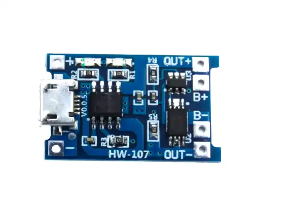
TP4056 1A Li-Ion Battery Charging Board Micro USB with Current Protection
The TP4056 is a classic example of precision CC/CV current limiting in IC form — charges Li-ion at exactly 1A CC then switches to CV at 4.2V. Perfect for studying and using current control in practice.
Transistor-Based Current Limiter
A classic two-transistor current limiter circuit provides reliable short-circuit protection and constant current behaviour. Here is how the most common topology works:
The Simple PNP/NPN Limiter (Current Sense + Pass Transistor)
Components needed: One NPN transistor (e.g., BC547 for low current, TIP41C for up to 6A), one PNP transistor (BC557 or TIP42C), one sense resistor (Rsense).
How it works:
- Rsense is placed in series with the load. As load current increases, the voltage across Rsense increases.
- When Vsense reaches approximately 0.6V (the base-emitter threshold of the NPN transistor), the NPN turns on.
- The NPN turning on pulls down the base of the PNP pass transistor, reducing its gate drive and thus limiting the current through the load.
- The circuit self-regulates — as current tries to exceed the limit, the feedback loop reduces the pass transistor’s conduction, maintaining constant current.
Set the current limit:
Ilimit = 0.6V / Rsense
Example: To limit current to 500mA, Rsense = 0.6 / 0.5 = 1.2Ω (use 1.2Ω, 1W resistor)
To limit to 1A: Rsense = 0.6 / 1 = 0.6Ω (use 0.56Ω or two 1.2Ω in parallel)
To limit to 2A: Rsense = 0.6 / 2 = 0.3Ω
Power dissipation in Rsense: P = I² × R = 1² × 0.6 = 0.6W at 1A limit — use a 1W or 2W resistor.
This circuit is used in countless power supplies, battery chargers, and motor drivers. It is inexpensive, reliable, and requires no special ICs.
Op-Amp Current Limiting Circuit
For more precise current limiting with better regulation, an op-amp based circuit provides superior performance. The op-amp compares the voltage across a sense resistor to a reference voltage and adjusts the pass element accordingly.
Basic op-amp current limiter topology:
- Sense resistor (Rs) in series with load — typically 0.1Ω to 1Ω
- Op-amp (LM358, TL071, or LM741) with non-inverting input connected to voltage divider reference
- Pass transistor (power MOSFET or Darlington BJT) in series with load, controlled by op-amp output
- Feedback from the sense resistor to op-amp inverting input
Current limit formula:
Ilimit = Vref / Rs
Where Vref is set by the voltage divider on the non-inverting input. Using a 10kΩ potentiometer as a voltage divider from a stable reference (e.g., 2.5V from an LM431) allows adjustable current limiting — extremely useful for a bench power supply build.
The op-amp provides much lower steady-state error than the simple transistor circuit, which has approximately ±10–20% variation in the 0.6V threshold due to transistor Vbe variations with temperature.

1S 12A 3.6V BMS Battery Protection Board for Li-ion Cell
This BMS board implements sophisticated current limiting at 12A to protect Li-ion cells — a real-world example of active current protection using dedicated ICs.
IC-Based Solutions: LM317 and Dedicated Chips
LM317 as a Constant Current Source
The LM317 adjustable voltage regulator can be configured as a precise constant current source with just two components — the IC and a sense resistor.
Circuit: Connect LM317 OUT pin to one end of Rs, the other end of Rs to load, ADJ pin to the junction between OUT and Rs. The LM317 maintains 1.25V between OUT and ADJ.
Ilimit = 1.25V / Rs
For 500mA: Rs = 1.25 / 0.5 = 2.5Ω (use 2.7Ω)
For 1A: Rs = 1.25Ω (use 1.2Ω)
For 200mA: Rs = 6.25Ω (use 6.2Ω)
The LM317 handles up to 1.5A output current in TO-220 package and provides excellent regulation. It also has built-in thermal shutdown and safe-area protection, making it highly robust for beginner designs.
Dedicated Current Limiting ICs
For more advanced applications, dedicated ICs like the following are popular:
- INA219: Current monitoring IC (I²C) — measures current and reports to microcontroller for software-based limiting
- TPS2490/TPS2491: Hot-swap controller with programmable current limiting — used in server-grade designs
- DW01A + 8205A: The protection IC combo found in most 18650 BMS boards — handles overcurrent, short circuit, and over-discharge cutoff
- PT4115: LED driver IC with adjustable constant current via a single resistor — used in LED lighting
Foldback Current Limiting for Battery Protection
Standard current limiting holds the current at a fixed maximum value even during a short circuit. This means the pass element must dissipate Vsupply × Ilimit — which can be substantial. For example, a 12V supply with 2A current limiting dumps 24W into the pass transistor during a dead short.
Foldback current limiting solves this: when the output voltage drops (due to overload or short), the current limit itself is reduced proportionally. This keeps the pass element’s power dissipation manageable during fault conditions while still protecting the load at normal voltages.
Foldback is implemented by feeding back the output voltage to reduce the reference voltage in the current limit comparator when Vout falls below a threshold. It is common in professional bench power supplies and battery chargers.
For most DIY projects, simple non-foldback current limiting is sufficient. Foldback becomes important when PD during short circuit would exceed the pass transistor’s safe operating area.

1S 18650 Li-ion Lithium Battery BMS Charger Protection Board for 3.7V Battery
Implements overcurrent, short-circuit, and overcharge protection for 18650 Li-ion cells. A ready-made current limiting solution for battery-powered projects.
Practical Applications for Indian Makers
1. First-Power-On Test Protection
Before applying full power to a new PCB, set your bench supply’s current limit to 50–100mA and watch the current reading as you power up. Normal circuits draw very little current at idle. If it immediately hits the current limit, there is likely a solder bridge or component orientation error to investigate before anything gets damaged.
2. LED Strip Power Supply
LED strips often have no current limiting of their own and rely entirely on the power supply. A current-limited supply or inline current limiter prevents one faulty LED section from dragging down the entire strip and overloading the supply.
3. Charging Non-Protected Li-ion Cells
If you have bare 18650 cells without built-in protection, use a TP4056-based charger (which implements CC/CV current limiting internally). Never charge bare Li-ion cells with a constant voltage source alone.
4. Motor Testing
When testing a new DC motor or during initial setup of a motor driver, current limiting prevents blown FETs if motor stall current exceeds expectations. Set the limit to 150% of rated motor current for normal operation, and test stall conditions carefully.
5. Solar Charge Controller (Manual)
If building a simple solar charger without a dedicated MPPT/PWM controller IC, an op-amp based constant current limiter prevents the solar panel from overcurrent-charging a battery when the panel is at peak output on a bright day.
Frequently Asked Questions
What is the difference between current limiting and a fuse?
A fuse is a one-time protection device — once it blows, it must be replaced. Current limiting is an active, continuous protection that restricts current automatically and recovers when the fault is removed. Fuses protect against catastrophic overcurrents; current limiters handle mild overloads and short-term faults. Use both: current limiting for normal overload protection, fuses as the last line of defence.
How do I choose the right sense resistor value?
The sense resistor value is determined by Ilimit = Vthreshold / Rsense. Use the lowest practical Vthreshold (0.1–0.2V for MOSFET-based, 0.6V for BJT-based) to minimise power loss in the sense resistor. Choose resistor power rating at least 2× the calculated I² × R dissipation.
Can I use a current limiting circuit for charging 18650 batteries?
Yes — Li-ion charging requires both current limiting (CC phase) and voltage limiting (CV phase). Use a dedicated charging IC like the TP4056 that implements both phases automatically, rather than designing this from scratch. The TP4056 is specifically designed for single-cell Li-ion CC/CV charging.
Will current limiting damage the pass transistor in a short circuit?
During a short circuit, the pass transistor must handle full supply voltage × limited current. Calculate PD = Vsupply × Ilimit and select a transistor rated for at least 2× this power with a heatsink. For high-power designs, MOSFET-based circuits with proper thermal management are more suitable than BJTs.
What is the simplest current limiter I can build right now?
An LM317 with a single resistor (Ilimit = 1.25 / R) is the simplest reliable constant current source you can build. It needs only three legs connected and a single resistor, is available at any components shop, handles up to 1.5A, and has built-in thermal protection.
Conclusion: Build Protection In, Not As an Afterthought
A current limiting circuit is not an optional add-on for advanced designs — it is a fundamental protection mechanism every electronic project benefits from. Whether you are driving LEDs, charging batteries, testing prototypes, or powering motors, adding current limiting protects your components, your power supply, and ultimately your investment of time and money in the project.
Start with the simplest approach that meets your needs: a series resistor for LEDs, an LM317 for adjustable constant current, or a TP4056 for Li-ion charging. As your projects grow in complexity, move to op-amp based designs and dedicated protection ICs.
Explore Zbotic’s full range of BMS boards, charging modules, and power management components — everything you need to build protected, reliable circuits.


Add comment