
Sensor circuits are only as accurate as the power rail feeding them. A noisy supply voltage corrupts ADC readings, causes I2C communication errors, and produces jitter in precision measurements. The solution is proper capacitor bank design for sensor power rail noise filtering — a fundamental skill that separates professional embedded designs from ones that work on the bench but fail in the field.
This guide covers the theory, component selection, PCB layout strategies, and practical design rules for building effective decoupling capacitor banks across all common sensor supply scenarios.
Noise Sources in Sensor Power Rails
Before designing a filter, understand what you are filtering. Sensor power rails carry several distinct types of noise:
Switching Regulator Ripple
Buck and boost converters operate at switching frequencies typically between 100 kHz and 2 MHz. They produce a periodic ripple voltage superimposed on the DC output. Amplitude is typically 10–50 mV peak-to-peak on a poorly filtered rail, but even 5 mV can visibly corrupt a 12-bit ADC reading (the LSB on a 5 V, 4096-count converter is 1.22 mV).
Digital Transients
Microcontrollers, FPGAs, and motor drivers draw burst currents when switching GPIO outputs. These current spikes travel through shared power and ground planes, coupling noise onto adjacent analog rails. A 32 MHz Arduino toggling a GPIO pin can produce 50–100 mV spikes on a 3.3 V rail with inadequate bypassing.
Inductive Load Kickback
Relays, solenoids, and motor coils generate voltage spikes when switched off. Even with flyback diodes, residual energy can couple into nearby supply wires and corrupt sensitive sensor measurements.
Ground Bounce
High-speed digital signals create rapidly changing currents in ground conductors. Because ground conductors have finite inductance (even a 10 cm wire has ~100 nH), these currents create small but significant voltage differences between the ground at the sensor and the ground at the microcontroller ADC reference pin.
Capacitor Types and Their Roles
Ceramic (MLCC) Capacitors
Multi-layer ceramic capacitors are the primary weapon against high-frequency noise. Their very low equivalent series inductance (ESL) makes them effective at filtering frequencies from 1 MHz to several hundred MHz. X5R and X7R dielectrics are preferred for power supply decoupling due to their stable capacitance across temperature and voltage.
Warning: Class 2 ceramics (X5R, X7R, Y5V) lose significant capacitance under DC bias voltage. A 10 µF / 6.3 V X5R capacitor may only deliver 2–3 µF when charged to 5 V. Always use a rated voltage at least 2x your operating voltage.
Electrolytic Capacitors
Aluminium electrolytics provide bulk capacitance (10 µF to thousands of µF) at low cost. Their relatively high ESR and ESL mean they are ineffective above a few hundred kHz. Use them to store charge for transient load demands, not to filter high-frequency noise.
Tantalum Capacitors
Better ESR and ESL than aluminium electrolytics, and physically smaller. Useful in space-constrained designs. However, tantalum capacitors can fail short-circuit when exposed to voltage spikes — always add a series resistor (typically 0.5–3.3 Ω) when using tantalum caps for supply decoupling.
Film Capacitors
Polypropylene film capacitors have excellent linearity and no DC bias effect on capacitance. Used primarily in audio-frequency filtering and precision reference circuits. Not typically used on digital supply rails due to their physical size.
ESR and ESL: The Hidden Parameters
Every real capacitor has three parasitic components in series: the equivalent series resistance (ESR), equivalent series inductance (ESL), and the capacitance itself. Together they form a series RLC circuit with a self-resonant frequency (SRF).
Below the SRF, the component behaves as a capacitor. Above the SRF, it behaves as an inductor — meaning it provides no filtering for frequencies above its SRF. A typical 100 nF 0402 MLCC has an SRF around 50–100 MHz. A 10 µF 1206 ceramic may resonate at only 5–10 MHz.
This is why a single large capacitor cannot filter all frequencies. You need parallel capacitors of different values, each covering its own frequency decade.
The Three-Tier Decoupling Strategy
Professional designs use three complementary tiers of capacitance, each targeting a different frequency range:
| Tier | Capacitance | Type | Target Frequency |
|---|---|---|---|
| 1 — Bulk | 47–470 µF | Electrolytic or tantalum | DC to 100 kHz |
| 2 — Local | 1–10 µF | X5R/X7R ceramic | 100 kHz – 10 MHz |
| 3 — High-Frequency | 10–100 nF | C0G/NP0 or X7R ceramic | 10 MHz – 500 MHz |
Place all three tiers as close as physically possible to the sensor’s VCC and GND pins, with the smallest capacitor closest to the IC.
Component Selection Guide
For 3.3 V Sensor Rails (ESP32, BME280, STM32)
- Bulk: 100 µF / 10 V aluminium electrolytic near the regulator output
- Local: 4.7 µF / 10 V X5R ceramic (0805 or 1206) per sensor cluster
- High-frequency: 100 nF / 10 V X7R ceramic (0402 or 0603) at each sensor VCC pin
For 5 V Digital Sensor Rails (Arduino, DHT22, HC-SR04)
- Bulk: 100–220 µF / 16 V electrolytic at the power entry point
- Local: 10 µF / 10 V X5R ceramic per sensor group
- High-frequency: 100 nF / 10 V X7R ceramic at each IC
For Precision Analog Sensor Rails (Load Cells, ACS712, INA219)
Analog circuits require extra attention. Add:
- A series ferrite bead between digital and analog supply
- 10 nF C0G (NP0) ceramic — this dielectric has near-zero capacitance variation with voltage and temperature, critical for precision references
- Separate star-point ground connection — never share a ground return with digital signals
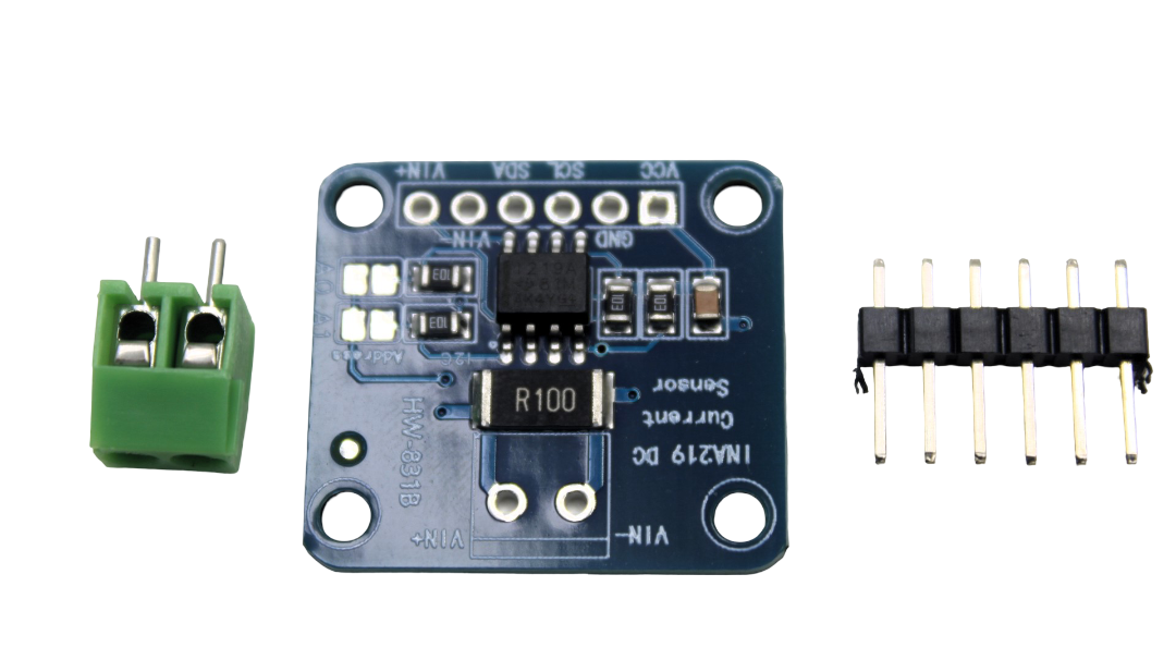
CJMCU-219 INA219 I2C Bi-directional Current Monitor
The INA219 is a precision current/power sensor — a perfect example of an analog sensor that benefits enormously from careful power rail decoupling.
PCB Layout Rules for Capacitor Banks
Component selection is only half the battle. PCB layout determines whether those components actually do what they are supposed to do.
Rule 1: Closest Capacitor First
Place the smallest decoupling capacitor closest to the IC’s VCC pin. Any trace length between the capacitor and the IC adds inductance that degrades high-frequency filtering. On a 0.2 mm trace, even 5 mm adds roughly 4 nH — enough to resonate with your 100 nF capacitor at only 25 MHz.
Rule 2: Via Between VCC Pad and Capacitor
If the decoupling capacitor is on the opposite side of the PCB from the IC (common in double-sided layouts), use two vias — one for VCC and one for GND — placed as close as possible to the IC pad. Each via adds ~1 nH.
Rule 3: Dedicated Ground Plane
Always use a continuous ground plane underneath sensor circuits. A ground plane provides a very low inductance return path for high-frequency currents. Split the ground plane only if absolutely necessary (analog vs digital ground) and connect the two at a single point near the ADC reference pin.
Rule 4: Avoid Daisy-Chaining
Do not run the power rail through a long daisy chain from component to component. Instead, star-route from a single low-impedance bulk capacitor node to each sensor’s local decoupling position.
Rule 5: Capacitor Orientation
When using multiple SMD capacitors in parallel, orient them so current flows in opposite directions. This mutual inductance cancellation (anti-parallel placement) reduces the effective ESL of the combination, improving high-frequency performance.
Bulk Capacitance: How Much Is Enough?
A useful rule of thumb for bulk capacitance is based on the transient load requirement:
C = I_transient × t / ΔV

Where:
  I_transient = peak current demand of the sensor cluster (A)
  t           = duration of the transient (s)
  ΔV          = allowable voltage droop (V)
Example: A group of 5 sensors each drawing 20 mA peak for 1 ms transitions, with a ±50 mV droop budget:
I_transient = 5 × 20 mA = 100 mA = 0.1 A
t = 1 ms = 0.001 s
ΔV = 0.05 V

C = 0.1 × 0.001 / 0.05 = 2,000 µF... way more than needed?
In practice, 100–470 µF bulk capacitance near the regulator covers most sensor clusters. The regulator’s feedback loop also replenishes the charge during the transient — the capacitor just needs to handle the initial droop before the regulator responds (typically 10–50 µs loop response time).
Ferrite Beads: When to Add Them
A ferrite bead is a frequency-dependent resistor. At low frequencies it is nearly transparent (milliohms impedance). At high frequencies (10 MHz and above) it presents significant impedance (50–1000 Ω depending on the bead), attenuating high-frequency noise from passing through.
Use ferrite beads:
- Between a switching regulator output and a sensitive analog sensor rail
- Between a digital power plane and a precision reference supply
- On every power and ground pin of RF modules (Bluetooth, Wi-Fi) to prevent RF from coupling into sensor supply rails
Do NOT use ferrite beads on high-current power rails — the DC resistance (typically 100–500 mΩ) causes a voltage drop and power dissipation that can be significant at currents above 500 mA.
The classic filter topology: 100 µF electrolytic → ferrite bead → 10 µF ceramic → 100 nF ceramic → sensor VCC pin.
Dedicated LDOs for Critical Sensors
Sometimes capacitor filtering alone is insufficient. For sensors with sub-1% ADC accuracy requirements, consider powering them from a dedicated low-noise LDO regulator rather than the main system supply.
A simple AMS1117-3.3 or HT7333 LDO fed from the 5 V rail provides a clean, regulated 3.3 V with excellent line regulation (variation in input has minimal effect on output). Even a noisy 5 V input from a switching supply translates to a very quiet 3.3 V output. Add the standard 10 µF + 100 nF output decoupling and the LDO’s PSRR (power supply rejection ratio) of 60–80 dB does the rest.
Sensor-Specific Decoupling Examples
BME280 / BMP280 Pressure Sensor
The Bosch datasheet specifies 100 nF + 10 µF on VDD and VDDIO separately. Non-compliance is the most common cause of compensation failures and stuck I2C buses on these sensors.
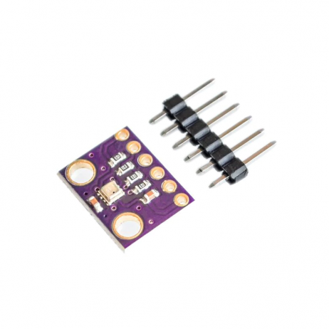
GY-BME280-3.3 Precision Altimeter Sensor Module
The BME280 measures temperature, pressure, and humidity simultaneously — proper power rail decoupling ensures accurate readings from all three channels.
DS18B20 Temperature Sensor (1-Wire)
The DS18B20 draws a large current pulse (~1.5 mA for 750 ms) during temperature conversion. A 100 µF capacitor on the VCC pin (for externally powered mode) prevents this from drooping the supply during conversion. In parasite-powered mode, an external strong pull-up MOSFET is required — capacitors alone are insufficient.

DS18B20 Programmable Resolution Temperature Sensor
The DS18B20’s parasite-power mode has specific decoupling requirements — a bulk capacitor near VCC prevents conversion errors.
MQ-series Gas Sensors (MQ-2, MQ-135)
The MQ sensor heater draws 150–250 mA at 5 V. This is a large transient load. Use a dedicated 1000 µF electrolytic on the heater supply, and separate the heater ground from the sensor signal ground to prevent heater current causing ground bounce in your ADC readings.
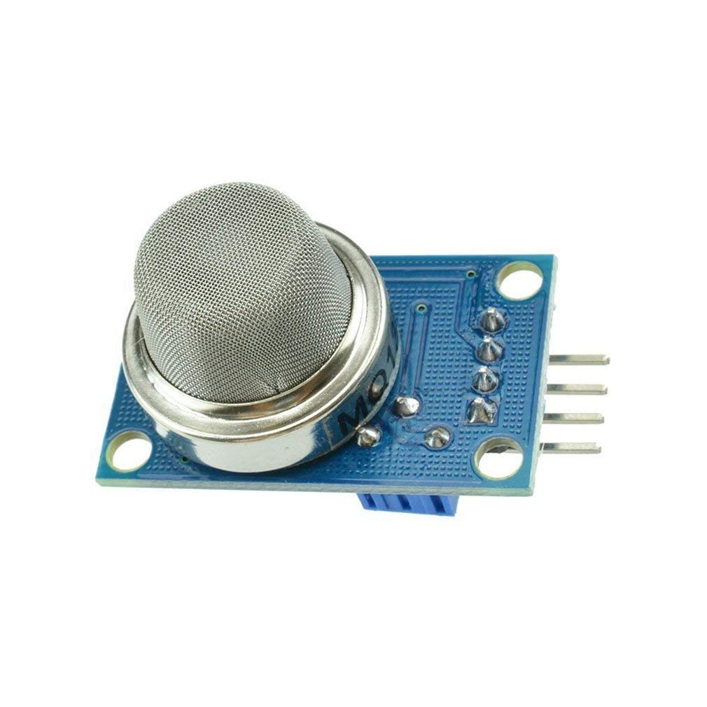
MQ-135 Air Quality/Gas Detector Sensor Module
The MQ-135’s 150+ mA heater is one of the most common causes of noisy ADC readings on shared sensor rails — power it with dedicated bulk capacitance.
Frequently Asked Questions
Q: Can I use a single 1000 µF capacitor instead of multiple smaller ones?
A: No. A large electrolytic has high ESL and is only effective at frequencies below ~100 kHz. You still need small ceramic capacitors (100 nF) at each IC for high-frequency decoupling. Use the large cap for bulk storage and the ceramics for fast filtering.
Q: Do I need decoupling on sensor modules that already have on-board capacitors?
A: Yes, if the sensor is farther than ~5 cm from a board-level bulk supply. The trace impedance between your power connector and the module still causes noise. Add at least a 100 nF ceramic at the module’s VCC connector pin.
Q: My DHT22 reads -1 intermittently. Could a noisy power rail be the cause?
A: Yes — it is one of the most common root causes. The DHT22 is sensitive to supply voltage dips during its single-wire communication. Add a 100 µF electrolytic + 100 nF ceramic on the VCC pin and place them as close to the module as possible.
Q: What capacitor value should I use for a 5 V Arduino Uno power pin?
A: Place a 100 µF / 25 V electrolytic on the VIN or 5 V pin near the power entry and a 100 nF ceramic per sensor connection point. The Arduino board itself has some decoupling but it is minimal for noisy environments.
Q: Is it harmful to use too much decoupling capacitance?
A: Excessive bulk capacitance can cause slow startup (large inrush current charges the capacitor bank) and may overwhelm some LDO regulators, causing oscillation. For LDOs, check the output capacitance stability range in the datasheet. For most applications, 100–470 µF is more than sufficient as bulk capacitance.
Conclusion
Proper capacitor bank design is one of the highest-leverage improvements you can make to a sensor circuit. The three-tier decoupling strategy — bulk electrolytic, local 10 µF ceramic, high-frequency 100 nF ceramic — combined with correct PCB layout and careful ground plane design, eliminates the majority of noise-related sensor failures. For precision sensors like load cells, current monitors, and pressure transducers, adding a ferrite bead and a dedicated LDO completes the filtering chain.
Explore Zbotic’s full range of sensors and measurement modules — designed to work reliably in the real-world circuits you build.
Shop Sensors & Measurement Modules
Find the right sensor for your project at Zbotic — fast delivery across India with technical support.


Add comment