
Table of Contents
- Project Overview
- Parts List
- Understanding the Pan-Tilt Mechanism
- Wiring the Servos to Arduino
- Basic Joystick Control Code
- Smooth Motion with Interpolation
- Face/Object Tracking with OpenCV (Bonus)
- Mechanical Assembly Tips
- Troubleshooting
- Frequently Asked Questions
A pan-tilt camera mount gives your security camera, FPV camera, or webcam two axes of motorised movement: left-right (pan) and up-down (tilt). With two servo motors and an Arduino, you can build a fully functional mount in an afternoon that responds to a joystick, follows a programmed sweep pattern, or even tracks faces using a Raspberry Pi and OpenCV.
This project is one of the best introductions to servo motor control because the mechanics are simple, the results are immediately visible and satisfying, and the skills — PWM control, servo calibration, smooth motion algorithms — transfer directly to robotic arms, gimbals, and automated camera systems.
Project Overview
We will build two versions of increasing complexity:
- Version 1 (Basic): Two SG90 servos, Arduino Uno, joystick module. Manual joystick control. Time to build: 1–2 hours.
- Version 2 (Advanced): Smooth interpolated motion, auto-sweep mode, serial command interface for integration with Python/OpenCV on a connected computer for face tracking.
The pan-tilt mount is also the foundation for: security camera systems, FPV turret systems, laser pointer games (shine a laser at wherever the joystick points), solar trackers (replace joystick with light sensors), and telescope auto-tracking mounts.
Parts List
| Component | Quantity | Notes |
|---|---|---|
| SG90 or TowerPro SG90 Servo | 2 | Pan axis + tilt axis |
| Arduino Uno or Nano | 1 | Any Arduino with Servo.h works |
| Pan-Tilt Bracket Kit (or 3D printed) | 1 | SG90-compatible bracket set |
| Joystick Module | 1 | Dual-axis analog joystick |
| External 5V supply (1A min) | 1 | Do NOT power servos from Arduino 5V |
| 100µF capacitors | 2 | One per servo, decoupling |
| Breadboard + jumper wires | 1 set | Prototyping |
| USB webcam or Pi Camera Module | 1 | Mount on the tilt servo platform |

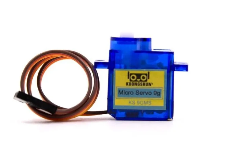
TowerPro SG90 180 Degree Rotation Servo Motor
The most popular micro servo for pan-tilt mounts — compact form factor fits standard brackets, 1.6 kg·cm at 6V, and genuine TowerPro quality vs no-name clones.

Servo Mount Holder Bracket For SG90/MG90 (Pack of 2)
Purpose-built metal servo mounting brackets for SG90 and MG90S — provides the rigidity needed for a stable pan-tilt camera platform that does not wobble.
Understanding the Pan-Tilt Mechanism
A pan-tilt mechanism is a 2-DOF gimbal:
- Pan axis (yaw / horizontal): The bottom servo rotates the entire assembly left-right around a vertical axis. The pan servo is fixed to the base; everything above it rotates with the horn.
- Tilt axis (pitch / vertical): The top servo rotates the camera platform up-down. This servo is carried by the pan servo’s output horn, so it sweeps left-right as the pan servo moves.
The mechanical challenge is the tilt servo’s cable — it must travel through or around the pan axis rotation without binding. Three solutions:
- Use a servo extension cable with enough slack to allow 90° pan either side (simplest)
- Route the cable through the pan servo axis centre (requires hollow-shaft bracket — rare)
- Use wireless signal transmission for the tilt servo (overkill for most projects)
For most pan-tilt mounts, solution 1 with a quality extension cable works perfectly for ±90° pan range.

10cm 60-Core JR Male to Futaba Female Servo Extension Wire
Short servo extension with locking hook — exactly the right length to route the tilt servo cable through a pan-tilt mount with enough slack for full rotation.
Wiring the Servos to Arduino
Power Architecture
Two SG90 servos can draw up to 400 mA combined under load. The Arduino’s 5V pin (from USB) supplies only 300–500 mA shared with the Arduino itself. Always use a separate 5V supply for the servos.
Recommended: a dedicated 5V/2A USB phone charger or a 7.5V supply into a 7805 regulator (3A rated). Connect the supply directly to the servo power (red) and ground (brown) wires. Connect only the signal (orange) wire to the Arduino GPIO pin.
Connection Table
| Servo Wire Colour | Pan Servo | Tilt Servo |
|---|---|---|
| Red (Power) | External 5V supply + | External 5V supply + |
| Brown/Black (GND) | Common GND (supply + Arduino) | Common GND |
| Orange/Yellow (Signal) | Arduino D9 | Arduino D10 |
Joystick module connections:
- VCC → Arduino 3.3V (or 5V)
- GND → Arduino GND
- VRx (horizontal) → Arduino A0
- VRy (vertical) → Arduino A1
- SW (button, optional) → Arduino D2 with INPUT_PULLUP
Basic Joystick Control Code
#include <Servo.h>

Servo panServo;    // Pan (left-right)
Servo tiltServo;   // Tilt (up-down)

const int PAN_PIN  = 9;
const int TILT_PIN = 10;
const int JOY_X    = A0;  // Pan joystick axis
const int JOY_Y    = A1;  // Tilt joystick axis

int panAngle  = 90;  // Centre position
int tiltAngle = 90;

void setup() {
  panServo.attach(PAN_PIN);
  tiltServo.attach(TILT_PIN);
  panServo.write(panAngle);
  tiltServo.write(tiltAngle);
  delay(500);  // Let servos settle at centre
}

void loop() {
  int joyX = analogRead(JOY_X);  // 0-1023
  int joyY = analogRead(JOY_Y);  // 0-1023

  // Dead zone: ignore small joystick movements (centre ±50)
  if (abs(joyX - 512) > 50) {
    // Map joystick to angle change speed
    int panDelta = map(joyX, 0, 1023, -3, 3);
    panAngle = constrain(panAngle + panDelta, 0, 180);
    panServo.write(panAngle);
  }

  if (abs(joyY - 512) > 50) {
    int tiltDelta = map(joyY, 0, 1023, 3, -3); // Invert Y if needed
    tiltAngle = constrain(tiltAngle + tiltDelta, 30, 150); // Limit tilt range
    tiltServo.write(tiltAngle);
  }

  delay(20);  // ~50 updates per second
}
The constrain() function is critical — it prevents the servo from trying to move beyond its physical stop, which would stall the motor and cause it to overheat. Set the tilt range to 30–150° to protect the camera cable from being pinched at extreme angles.
Smooth Motion with Interpolation
The basic code makes the servo jump step-by-step, which looks mechanical and stresses the gears. This improved version uses linear interpolation (lerp) to smoothly ease toward the target angle:
#include <Servo.h>

Servo panServo, tiltServo;

float panCurrent  = 90.0;
float tiltCurrent = 90.0;
float panTarget   = 90.0;
float tiltTarget  = 90.0;

const float SMOOTH = 0.1;  // Smoothing factor: 0=no movement, 1=instant

void setup() {
  Serial.begin(9600);
  panServo.attach(9);
  tiltServo.attach(10);
  panServo.write(90);
  tiltServo.write(90);
  delay(500);
}

void updateFromJoystick() {
  int jx = analogRead(A0);
  int jy = analogRead(A1);
  if (abs(jx - 512) > 50) panTarget  += map(jx, 0, 1023, -2, 2);
  if (abs(jy - 512) > 50) tiltTarget += map(jy, 0, 1023, 2, -2);
  panTarget  = constrain(panTarget,  0,   180);
  tiltTarget = constrain(tiltTarget, 30,  150);
}

// Serial command format: "P90 T45n" sets pan=90, tilt=45
void updateFromSerial() {
  if (Serial.available()) {
    String cmd = Serial.readStringUntil('n');
    if (cmd.startsWith("P")) {
      int tIdx = cmd.indexOf('T');
      if (tIdx > 0) {
        panTarget  = cmd.substring(1, tIdx).toFloat();
        tiltTarget = cmd.substring(tIdx+1).toFloat();
      }
    }
  }
}

void loop() {
  updateFromJoystick();
  updateFromSerial();

  // Lerp current toward target
  panCurrent  += (panTarget  - panCurrent)  * SMOOTH;
  tiltCurrent += (tiltTarget - tiltCurrent) * SMOOTH;

  panServo.write((int)panCurrent);
  tiltServo.write((int)tiltCurrent);

  delay(20);
}
The SMOOTH factor controls response speed. At 0.1, the servo reaches 90% of its target in about 22 update cycles (440 ms) — natural-feeling motion. Increase to 0.3 for faster but still smooth response. The serial command interface (format: P90 T45) lets you control the mount from Python on a connected computer.
Face/Object Tracking with OpenCV (Bonus)
Connect the Arduino to a Raspberry Pi or laptop via USB. The computer runs OpenCV for detection; the Arduino handles servo control. Python script on the computer:
import cv2
import serial
import time

# Connect to Arduino
ser = serial.Serial('/dev/ttyUSB0', 9600, timeout=1)  # Linux
# ser = serial.Serial('COM3', 9600, timeout=1)        # Windows
time.sleep(2)  # Wait for Arduino reset

cap = cv2.VideoCapture(0)
face_cascade = cv2.CascadeClassifier(
    cv2.data.haarcascades + 'haarcascade_frontalface_default.xml')

pan_angle  = 90
tilt_angle = 90

while True:
    ret, frame = cap.read()
    if not ret:
        break

    h, w = frame.shape[:2]
    gray = cv2.cvtColor(frame, cv2.COLOR_BGR2GRAY)
    faces = face_cascade.detectMultiScale(gray, 1.1, 4)

    if len(faces) > 0:
        # Track the largest detected face
        x, y, fw, fh = max(faces, key=lambda f: f[2]*f[3])
        cx = x + fw//2
        cy = y + fh//2

        # Calculate error from frame centre
        err_x = cx - w//2
        err_y = cy - h//2

        # Proportional control
        pan_angle  -= int(err_x * 0.05)
        tilt_angle += int(err_y * 0.05)
        pan_angle  = max(0,  min(180, pan_angle))
        tilt_angle = max(30, min(150, tilt_angle))

        cmd = f"P{pan_angle} T{tilt_angle}n"
        ser.write(cmd.encode())

        cv2.rectangle(frame, (x,y), (x+fw, y+fh), (0,255,0), 2)

    cv2.imshow('Pan-Tilt Tracker', frame)
    if cv2.waitKey(1) & 0xFF == ord('q'):
        break

cap.release()
cv2.destroyAllWindows()
ser.close()
Install dependencies with: pip install opencv-python pyserial. The proportional gain (0.05) may need tuning — increase for faster tracking, decrease if the mount oscillates around the target face.
Mechanical Assembly Tips
Centring Servos Before Assembly
Always centre both servos (write(90)) before attaching any brackets or horns. This ensures the mechanical zero position aligns with the software 90° position. If you attach the horn to a servo at an arbitrary position, the arm might hit its physical limit at 45° while the code thinks it is at 90°.
Base Stability
Mount the base servo to a heavy, flat surface (wooden base, metal plate, or 3D-printed weighted base). A light base causes the whole mount to wobble as the pan servo reverses direction — the inertia of the upper assembly is significant. Add adhesive rubber feet to prevent sliding.
Camera Mounting
For a USB webcam: remove the base clip and hot-glue the camera body to the tilt servo’s upper platform (or use M2 screws into the horn holes). For a Raspberry Pi Camera Module: 3D print a small bracket that slides onto standard servo horn mounting holes — many designs are available on Thingiverse for free.
Cable Management
Route servo cables through small zip-tie loops or cable clips along the pan bracket’s edge. Leave enough slack between the base and the pan servo (at least 3× the loop for ±90° range) but not so much that the cable catches on the bracket during rotation.
Servo SG90 9g 180 Degree
An affordable SG90-format servo — great for your second axis or for prototyping the tilt mechanism before investing in premium servos for the final build.
Troubleshooting
Servo jitters even when joystick is centred
The joystick’s centre position rarely reads exactly 512 — it floats ±20–50 counts. The dead zone in the code (50 counts) handles this. If jitter persists, increase the dead zone to 80 counts. Also check for noise on the 5V supply — add a 100µF capacitor between 5V and GND at the servo power rail.
Pan servo moves opposite to expected direction
Swap the pan joystick axis mapping: change map(joyX, 0, 1023, -3, 3) to map(joyX, 0, 1023, 3, -3). Alternatively, physical rotation direction depends on how you oriented the servo in the bracket — both mounting orientations are equally valid mechanically.
Servo makes grinding noise at certain angles
The servo is reaching its mechanical stop (gears hitting the internal stop pin). Tighten your angle constraints in constrain(). For tilt, never command below 10° or above 170° unless you have confirmed your specific servo mechanism allows it.
Face tracking oscillates around the target (hunting)
Reduce the proportional gain (change 0.05 to 0.02). Add a dead zone: only command a servo move if abs(err_x) > 20 pixels. The SMOOTH factor in the Arduino code also helps damp oscillation — increase it slightly.
Serial commands not received by Arduino
Verify baud rate matches (9600 in both Python and Arduino). The Arduino resets when a serial connection opens — the 2-second time.sleep(2) in Python is essential. Use ser.readline() to check if Arduino is sending any debug output.
Frequently Asked Questions
Can I use MG996R servos instead of SG90 for the pan-tilt mount?
Yes, and it is recommended if your camera weighs more than 60 g (DSLR lens, action camera with heavy housing). MG996R provides 9–11 kg·cm vs SG90’s 1.6 kg·cm. You will need to use MG996R-compatible brackets, which are larger, and adjust your power supply to at least 5A at 6V for two MG996R servos under load.
How do I add a third axis (roll) to this pan-tilt mount?
Mount a third servo on the tilt platform’s output shaft, perpendicular to the tilt axis. This gives you a full 3-axis gimbal. You now need three signal wires to three Arduino PWM pins, and correspondingly a third joystick axis (use the joystick button press as a mode switch, or use a second joystick, or add a rotary encoder for roll).
What is the difference between a pan-tilt mount and a gimbal?
A pan-tilt mount is manually or programmatically positioned — you command it to go to specific angles. A gimbal is a stabilisation system — it continuously corrects for external motion (hand shake, vehicle vibration) to keep the camera pointing at a fixed orientation. Gimbals use inertial measurement units (IMU: gyroscope + accelerometer) and high-frequency control loops (1000+ Hz) compared to a pan-tilt mount’s simple position commands.
Can I run this project entirely on battery power?
Yes. Use a 6V 4xAA battery pack or a 2S LiPo (7.4V) with a 5V step-down regulator. Power both the Arduino (via Vin pin or USB from regulator) and the servos from the same 5V regulated rail. A 2000 mAh LiPo gives approximately 4–6 hours of operation at typical intermittent use (servos only draw full current when moving).
How do I add Bluetooth control to this pan-tilt mount?
Replace or supplement the serial connection with an HC-05 or HC-06 Bluetooth module. Connect the module’s TX/RX to Arduino D10/D11 (via SoftwareSerial). Use a Bluetooth serial terminal app on your phone to send the same P90 T45 commands. Range is typically 10m indoors — sufficient for a room-sized security camera turret.
Start Building Today
A pan-tilt servo camera mount is one of the most satisfying weekend projects you can build: it combines clean mechanical design, straightforward electronics, and immediately impressive visual results. Start with basic joystick control, then add the serial interface and face tracking once you are comfortable with the hardware. All the servo motors, brackets, and extension cables you need are available from Zbotic with fast delivery across India.


Add comment