
A fixed solar panel captures only a fraction of the sunlight it could if it were always pointed directly at the sun. A solar tracker changes this by rotating the panel to follow the sun’s path across the sky, boosting energy capture by 25–45% depending on the season and latitude. This project guide builds a complete dual-axis automatic solar tracker using two servo motors, four LDR (light-dependent resistor) sensors, and an Arduino Uno — all components readily available in India at low cost.
How a Solar Tracker Works
The sun moves approximately 15° per hour across the sky from east to west, and its elevation above the horizon changes seasonally. A dual-axis tracker compensates for both axes: azimuth (east-west rotation) and elevation (tilt angle). A single-axis tracker follows only azimuth; a dual-axis tracker follows both, capturing the maximum possible solar energy at any time of year.
The LDR-based tracking method uses a simple differential light measurement. Four LDRs are arranged in a cross pattern on the panel, separated by physical dividers (cardboard fins or 3D printed separators). The dividers cast shadows on adjacent LDRs when the panel is not pointed at the brightest light source. The Arduino reads voltage dividers connected to each LDR, compares pairs (top vs bottom for elevation, left vs right for azimuth), and moves the servos to reduce the difference. When all four LDRs read equal illumination, the panel is pointing directly at the sun.
This is a feedback control loop: error (difference in LDR readings) drives the correction signal (servo movement), and the loop runs continuously at whatever update rate the Arduino achieves (typically 50–200 ms per iteration).
Components List
All components for this project are available at Zbotic. You will need:
- 1× Arduino Uno R3
- 2× Servo motor (SG90 or MG996 depending on panel size)
- 4× LDR (GL5528 or equivalent 10 kΩ at 10 lux)
- 4× 10 kΩ resistors (for voltage dividers)
- 1× Small solar panel (5 V, 1 W for demonstration; scale up for real energy harvesting)
- 1× Breadboard and jumper wires
- Cardboard or 3D printed cross divider for LDR mount
- Servo arm extension or custom bracket for two-axis rotation
- 5 V power supply (USB or dedicated 5 V 2 A adapter)
For a demonstration model driving a 5×7 cm solar panel, SG90 servos provide adequate torque (1.8 kg-cm). For a panel larger than 20×20 cm, upgrade to MG996 (13 kg-cm) or a metal-gear servo for the elevation axis which bears the panel weight.
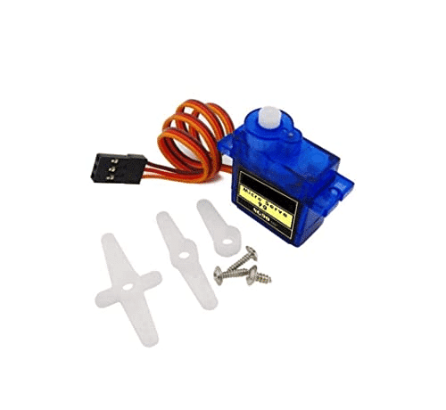
TowerPro SG90 180 Degree Rotation Servo Motor
Lightweight 9g servo with 1.8 kg-cm torque. Perfect for small solar tracker demos with panels up to 15×15 cm.
LDR Sensor Theory and Placement
An LDR (Light Dependent Resistor, also called photoresistor) reduces its resistance as light intensity increases. In darkness a GL5528 reads ≈1 MΩ; in bright sunlight it drops to 1–5 kΩ. Connected in a voltage divider with a fixed 10 kΩ resistor to 5 V, the midpoint voltage rises as light increases. The Arduino’s ADC reads this as a 0–1023 value (0 = dark, 1023 = bright).
For tracking, the four LDRs are labelled Top-Left (TL), Top-Right (TR), Bottom-Left (BL), Bottom-Right (BR) and mounted at the corners of the panel, separated by cross-shaped fins. The fins should be approximately the same height as the LDR spacing — about 15–20 mm for LDRs spaced 20 mm apart. Taller fins give more sensitivity (the shadow appears sooner when misaligned) at the cost of reduced range.
The error signals are computed as:
- Horizontal error: (TL + BL) − (TR + BR) → positive means more light on the left → move azimuth servo left
- Vertical error: (TL + TR) − (BL + BR) → positive means more light on top → move elevation servo up
A dead-band threshold (typically ±50 ADC counts out of 1023) prevents the servos from hunting constantly for the exact optimum. When the error is within the dead-band the servos hold position.
Circuit Diagram and Wiring
The wiring for this project is straightforward. Each LDR forms one arm of a voltage divider with a 10 kΩ pull-down resistor between the LDR and ground. The midpoint connects to an Arduino analogue input.
LDR wiring (repeat for all 4):
- 5 V → LDR → junction point → 10 kΩ → GND
- Junction point → Arduino A0 (TL), A1 (TR), A2 (BL), A3 (BR)
Servo wiring:
- Azimuth servo (horizontal): Signal → Arduino pin 9, Red → 5 V, Brown/Black → GND
- Elevation servo (vertical): Signal → Arduino pin 10, Red → 5 V, Brown/Black → GND
Important power notes: Do not power both servos from the Arduino’s 5 V pin. The Arduino’s on-board regulator can only supply about 300–400 mA. Two SG90 servos at load can draw 400–600 mA combined. Use a separate 5 V power supply for the servos. Connect the GND of the servo power supply to Arduino GND (common ground reference).
If using an external 5 V 2 A adapter: connect the adapter’s negative to Arduino GND and to both servo brown/black wires. Connect adapter positive to both servo red wires. Power the Arduino via USB separately or from the same adapter via the Vin pin (with a suitable voltage regulator if the adapter is 5 V exactly — use the 5 V pin directly, not Vin which goes through the Arduino’s internal regulator).
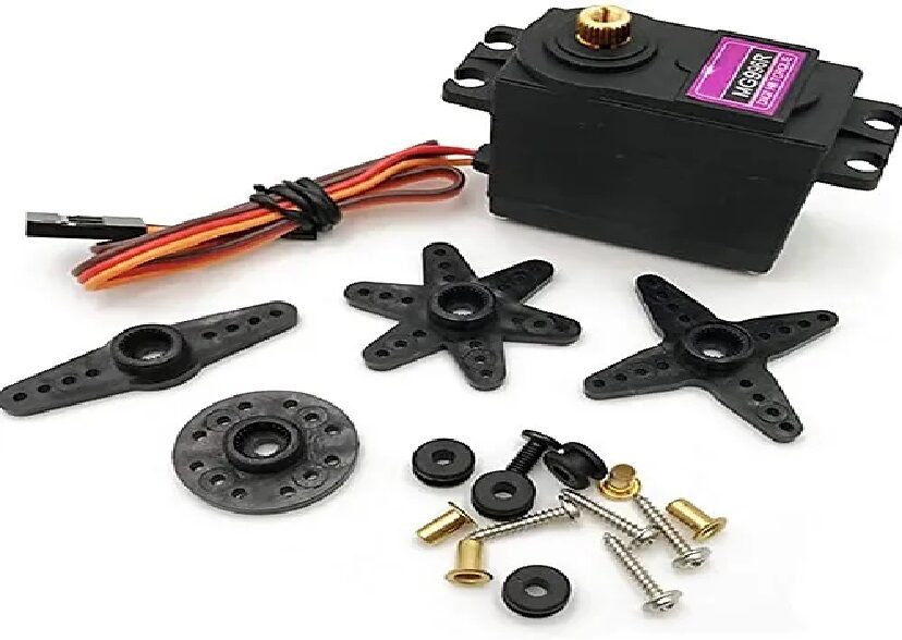
Servo MG996 13KG 180 Degree
Metal-gear servo with 13 kg-cm torque. Use on the elevation axis when tracking with panels larger than 20×20 cm or in outdoor wind-exposed installations.
Arduino Code
The complete Arduino sketch for a dual-axis LDR solar tracker:
#include <Servo.h>

Servo azimuthServo;   // Horizontal (East-West)
Servo elevationServo; // Vertical (Tilt)

// LDR analog pins
const int TL_PIN = A0; // Top-Left
const int TR_PIN = A1; // Top-Right
const int BL_PIN = A2; // Bottom-Left
const int BR_PIN = A3; // Bottom-Right

// Servo positions (degrees, 0-180)
int azimuth   = 90;
int elevation = 90;

// Tuning parameters
const int DEADBAND  = 50;   // ADC counts — increase to reduce hunting
const int STEP      = 1;    // Degrees per correction step
const int MIN_AZ    = 30;   // Minimum azimuth (don't over-rotate)
const int MAX_AZ    = 150;  // Maximum azimuth
const int MIN_EL    = 20;   // Minimum elevation (sunrise angle)
const int MAX_EL    = 160;  // Maximum elevation (zenith)
const int LOOP_MS   = 100;  // Update interval in milliseconds

void setup() {
  azimuthServo.attach(9);
  elevationServo.attach(10);
  azimuthServo.write(azimuth);
  elevationServo.write(elevation);
  Serial.begin(9600);
  delay(1000); // Allow servos to reach start position
}

void loop() {
  int tl = analogRead(TL_PIN);
  int tr = analogRead(TR_PIN);
  int bl = analogRead(BL_PIN);
  int br = analogRead(BR_PIN);

  int horizError = (tl + bl) - (tr + br); // Left vs Right
  int vertError  = (tl + tr) - (bl + br); // Top vs Bottom

  // Horizontal (azimuth) correction
  if (horizError > DEADBAND && azimuth > MIN_AZ) {
    azimuth -= STEP;  // Move left
  } else if (horizError < -DEADBAND && azimuth < MAX_AZ) {
    azimuth += STEP;  // Move right
  }

  // Vertical (elevation) correction
  if (vertError > DEADBAND && elevation < MAX_EL) {
    elevation += STEP; // Tilt up
  } else if (vertError < -DEADBAND && elevation > MIN_EL) {
    elevation -= STEP; // Tilt down
  }

  azimuthServo.write(azimuth);
  elevationServo.write(elevation);

  Serial.print("Az:"); Serial.print(azimuth);
  Serial.print(" El:"); Serial.print(elevation);
  Serial.print(" HErr:"); Serial.print(horizError);
  Serial.print(" VErr:"); Serial.println(vertError);

  delay(LOOP_MS);
}
Upload this sketch to your Arduino Uno. Open the Serial Monitor at 9600 baud to watch the tracker in real time. Cover individual LDRs with your finger to verify the servos respond in the correct direction. If a servo moves the wrong way, swap the signs in the correction block (change -= STEP to += STEP and vice versa).
Mechanical Assembly
The mechanical design requires two servo axes at 90° to each other:
Base (azimuth) servo: Mounted flat on the base plate with the servo horn pointing upward. The elevation platform rotates on this servo. Use an aluminium servo horn with a central hole for a bolt to accept the elevation servo mount.
Elevation servo: Mounted on the rotating platform (connected to the azimuth horn) with its axis horizontal. The solar panel bracket connects to this servo’s horn and rotates to change tilt angle.
For the LDR mount, cut a 40 mm × 40 mm square of cardboard. Draw a cross (+) from corner to corner and glue 10 mm tall cardboard fins along both lines, creating four quadrants. Glue one LDR face-up in each quadrant so the fins cast differential shadows. Attach this LDR assembly to the same surface as the solar panel, oriented identically.
The separation between the LDR array and the solar panel does not affect tracking quality — the LDRs measure relative light direction, not the panel’s electrical output. Mount them together rigidly so they always face the same direction.
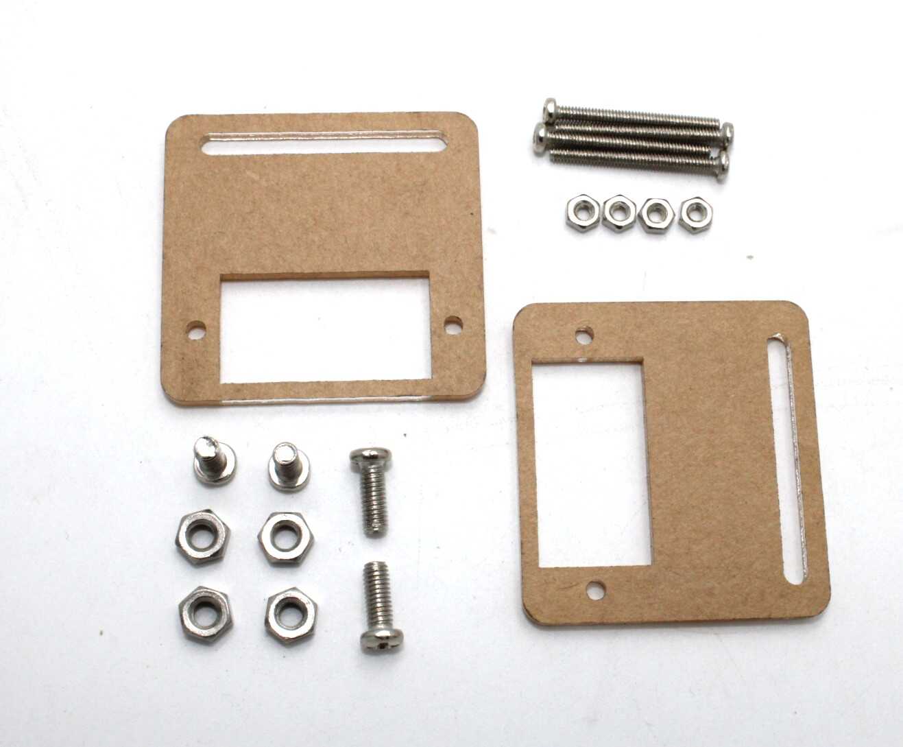
Servo Mount Holder Bracket for SG90/MG90 (Pack of 2)
Pre-drilled aluminium brackets for rigidly mounting SG90/MG90 servos. Essential for building a stable dual-axis tracker frame.
Calibration and Fine-Tuning
Deadband calibration: Start with DEADBAND = 50. If the servos hunt constantly (oscillating back and forth) in stable light, increase to 80–100. If the tracker is slow to respond to slow light changes, reduce to 30. The ideal deadband is the minimum value at which the servos are stable on a clear day.
Step size: The STEP parameter (default 1 degree) controls how quickly the tracker corrects. A larger step (2–3 degrees) makes the tracker faster but causes overshoot oscillation. A smaller step (0.5 degrees with fractional servo position) is smoother but slower. For an outdoor tracker on a slow 50 Hz loop, 1 degree per loop cycle (10 degrees per second) is adequate.
Low-light behavior: LDR-based trackers behave erratically on overcast days when diffuse light comes from all directions equally and the LDR differential reads near zero. Add a light intensity check: if the average of all four LDRs is below a threshold (e.g., 200 ADC counts ≈ overcast), freeze the servo positions rather than hunting for a peak that does not exist.
Night return: At sunset the tracker will have rotated to the western extreme. Add logic to return to the east-facing starting position (azimuth = MIN_AZ, elevation = 45°) when total light falls below a very low threshold (e.g., 50 ADC counts average). This prepares the tracker for sunrise without relying on motor limit switches.
Performance and Energy Gain
The energy gain from tracking depends on season, latitude, and the number of tracking axes:
- Single-axis (azimuth only): 20–35% gain over fixed mount
- Dual-axis (azimuth + elevation): 30–45% gain over fixed mount
In India at approximately 20°N latitude, a dual-axis tracker provides the greatest benefit in winter when the sun’s maximum elevation is only 46° — a panel tilted at a fixed 20° optimal annual angle loses significant elevation-axis energy during winter months.
To measure the gain experimentally, connect a digital multimeter or ammeter in series with the solar panel output and record current every 15 minutes over a clear day with tracking active, then again over an identical day with the servos locked in the annual-optimum fixed position. The ratio of daily energy totals gives the tracking gain factor.
Upgrades: RTC, GPS, and Astro Tracking
The LDR method is simple and low-cost but has limitations: it cannot work in cloud cover, and it can be confused by reflections from shiny surfaces. Two upgrades address these issues:
RTC-based hybrid tracking: Add a DS3231 RTC module. At night or in overcast conditions, calculate the sun’s expected position from date, time, and your fixed GPS coordinates using the Spencer solar position algorithm. This keeps the panel aimed correctly even when LDR feedback is unavailable. On a clear day, switch to LDR feedback for fine adjustment.
Pure astronomical tracking: Use a pre-computed lookup table of azimuth/elevation pairs for your location and time of year, stored in EEPROM. No sensors needed — purely time-driven. Less accurate than hybrid (misses fine corrections from atmospheric refraction and surface reflections) but completely reliable in any weather.
Stepper motor upgrade: For large panels (>0.5 m²) in permanent installations, replace servos with NEMA 17 stepper motors and lead screw actuators. Steppers hold position without power (no servo jitter), have much higher torque, and position precisely without a feedback pot that can wear out.

Aluminum Servo Horn/Arm 25T Round Disc for MG995/MG996
Metal servo horn for high-torque connections between the servo and tracker frame. Prevents the plastic horn from stripping under panel wind loads.
Frequently Asked Questions
Does a solar tracker actually save electricity in practice?
Yes, but the payback calculation depends on your electricity rate and the tracker’s construction cost. For demonstration models the energy gain is real (verifiable with a multimeter) but the cost per watt gained is high. For rooftop arrays of 1 kW or more, a dual-axis tracker typically recovers its build cost in 2–4 years in Indian sunlight conditions.
How many LDRs do I need for solar tracking?
A minimum of two LDRs enables single-axis tracking (one pair for azimuth). Four LDRs (two pairs) enable dual-axis tracking. Using more LDRs (e.g., a 3×3 grid of nine) can improve accuracy slightly but complicates the averaging logic without proportional benefit. Four LDRs in a quadrant arrangement is the industry-standard minimum for dual-axis tracking.
What is the maximum panel size these SG90 servos can move?
The SG90’s 1.8 kg-cm torque limits it to panels weighing under 100 g, approximately a 10×15 cm monocrystalline panel. For larger panels, use MG996 (13 kg-cm) for panels up to about 800 g. For panels above 1 kg, consider geared DC motors with encoders or NEMA 17 steppers with lead screws.
Can I use this tracker outdoors in rain?
The basic electronics are not waterproof. For outdoor use, enclose the Arduino and servo electronics in a weatherproof IP65 box. Use UV-stabilised servo leads. Seal LDR wiring connections with silicone. The servo motors themselves (SG90/MG996) are not IP-rated and will corrode over months of outdoor exposure — apply a thin coat of conformal coating to the PCB and servo connector pins.
Why does my tracker jitter constantly on a sunny day?
Jitter indicates the deadband is too small for your LDR sensitivity or that your power supply is causing ADC noise. First, increase DEADBAND from 50 to 100 and observe. If jitter continues, add 100 nF ceramic capacitors between each LDR midpoint and GND to filter noise, and power the Arduino from a clean USB supply rather than a switching regulator on the same breadboard as the servos.
Can I use stepper motors instead of servos for solar tracking?
Yes and this is recommended for panels above 500 g or for permanent outdoor installations. Stepper motors with microstepping drivers give finer angular resolution (0.1° with 1/16 stepping on a 200-step NEMA 17), hold position without any power draw between corrections (compared to servo humming under constant load), and are available with much higher torque in a compact NEMA 17 or NEMA 23 form factor.
Get Your Solar Tracker Components at Zbotic
Zbotic stocks SG90, MG90, and MG996 servo motors, servo mounting brackets, and a wide range of sensors and actuators for your next solar energy or robotics project.


Add comment