
LiDAR (Light Detection and Ranging) technology has rapidly moved from the domain of military satellites and expensive survey aircraft into the reach of advanced hobbyists, researchers, and small engineering teams in India. A drone-mounted LiDAR sensor, combined with ArduPilot’s autonomous flight capabilities and the Robot Operating System (ROS) for data handling, creates a powerful terrain mapping system capable of generating centimetre-accurate 3D point clouds of forests, mines, construction sites, and archaeological sites — even in conditions where photogrammetry fails, such as dense tree canopy or poor lighting.
This project guide walks you through building a complete drone LiDAR terrain mapper from hardware selection and assembly through sensor integration, ArduPilot configuration, ROS pipeline setup, and final data processing. It is written for technically capable builders in India who are comfortable with Linux, Python/C++, and drone construction basics.
1. Why LiDAR Over Photogrammetry?
Both photogrammetry and LiDAR produce 3D spatial data, but they do so through fundamentally different means and excel in different scenarios.
LiDAR Advantages
- Penetrates vegetation: LiDAR pulses can pass through gaps in a forest canopy and return ground returns even under dense trees. Photogrammetry cannot see through vegetation at all.
- Works in any lighting: LiDAR is an active sensor — it emits its own laser pulses. It works equally well at dawn, dusk, or in overcast conditions. Photogrammetry requires good lighting.
- True point cloud with density control: LiDAR produces explicit 3D point measurements with intensity values. Each return is a precise range measurement, not a reconstruction artifact.
- Multiple returns: Many LiDAR sensors support dual returns — the first return (from the top of a tree canopy) and the last return (from the ground underneath) are recorded separately, enabling accurate Digital Terrain Models (DTMs) even under forest cover.
LiDAR Disadvantages
- Significantly more expensive than camera-based photogrammetry
- Does not produce texture/colour information (though can be fused with camera data)
- Heavier and more power-hungry than cameras — affects drone flight time
- More complex data processing pipeline
Indian Applications for Drone LiDAR
LiDAR is particularly valuable in India for:
- Forest canopy and biomass estimation for the Forest Survey of India
- Mining surveying in Jharkhand, Chhattisgarh, and Odisha
- Archaeological site mapping (India has thousands of unexcavated or partially mapped heritage sites)
- Flood modelling and watershed delineation for water resource management
- Power line and transmission corridor inspection
2. System Architecture Overview
Our drone LiDAR terrain mapper consists of several integrated systems that must communicate seamlessly:
[LiDAR Sensor] ──USB/Serial──► [Companion Computer (Raspberry Pi / Jetson Nano)]
                                          │
[High-Precision GNSS/RTK] ─Serial─►      │ (ROS running)
                                          │
[ArduPilot FC (Pixhawk)] ───MAVLink────►  │
        │                                 │
[IMU (built-in to FC)]                    │
                                          │
                               [rosbag Recording → SD Card]
                                          │
                               [Post-flight Processing]
                                          │
                               [CloudCompare / PDAL / QGIS]
The key insight is that accurate LiDAR mapping requires three things to happen simultaneously and be precisely time-stamped:
- LiDAR point cloud — where is each laser pulse hitting?
- Drone position — where is the drone when each pulse is fired?
- Drone orientation (attitude) — which direction is the LiDAR pointing (roll, pitch, yaw)?
ROS’s message timestamping system and the MAVROS package (which bridges ArduPilot to ROS) make this synchronisation manageable, though not trivial.
3. Hardware Selection and Bill of Materials
Drone Frame
For a LiDAR payload, you need a sturdy hexacopter or large quadcopter capable of lifting 1–3kg payload in addition to its own weight and battery. The EFT 6120 surveillance frame is well-suited to this application — its modular construction allows a central payload bay where the LiDAR and companion computer can be mounted with vibration isolation.
LiDAR Sensor Options
LiDAR sensors span a massive price range. For an Indian research or small-business budget:
| Sensor | Range | Points/sec | Weight | Approx. Price |
|---|---|---|---|---|
| Livox Mid-360 | 40m | 200K | 265g | ~₹1.5L |
| Velodyne VLP-16 | 100m | 300K | 830g | ~₹8L |
| Ouster OS0-32 | 50m | 655K | 447g | ~₹5L |
| RPLIDAR A3 (2D) | 25m | 16K | 190g | ~₹25K |
For a first LiDAR drone project, the Livox Mid-360 offers an excellent balance of capability and cost. It has a non-repetitive scanning pattern (better point density than spinning LiDARs of similar price) and is popular in the ROS community with good driver support.
Complete Bill of Materials
- Drone frame: EFT 6120 hexacopter or similar heavy-lift frame
- Motors: T-Motor A10-KV120 (×6) or equivalent heavy-lift motors
- ESCs: 40A brushless ESCs (×6) or equivalent 6-in-1 ESC
- Flight controller: Pixhawk 6C or CubePilot Orange (ArduPilot-compatible)
- GPS/GNSS: Here3+ RTK GPS (dual-antenna for heading) or u-blox F9P RTK module
- Companion computer: Raspberry Pi 5 (8GB) or NVIDIA Jetson Orin NX
- LiDAR sensor: Livox Mid-360 or Velodyne VLP-16 (budget-dependent)
- Battery: 6S 10,000–16,000mAh LiPo (×2 for extended flight)
- Storage: High-speed NVMe SSD for companion computer, USB 3.1 enclosure
- Telemetry: 3DR 915MHz radio telemetry set
- Vibration isolation: Damped payload mount (custom or commercial)
4. Drone Frame Assembly
The assembly of a heavy-lift drone for LiDAR mapping is similar to a standard multirotor build, with extra attention paid to payload mounting and vibration isolation.
Vibration Isolation — Critical for LiDAR Accuracy
Motor vibrations corrupt LiDAR scans by introducing jitter into the sensor’s position during scanning. This results in point clouds that look “smeared” along the flight direction. The solution is a high-quality vibration-isolated mount for the entire payload system (LiDAR + companion computer + IMU).
Use a sandwich of 60A Shore hardness silicone vibration dampers between the frame and payload platform. Soft (low Shore hardness) mounts absorb high-frequency vibration but allow more low-frequency movement. The goal is to isolate the 100–300Hz motor vibration frequency while allowing the payload to follow slow drone body attitude changes.
LiDAR Orientation
Mount the LiDAR pointing downward (nadir) for terrain mapping. Ensure the sensor’s coordinate system is documented relative to the drone’s body frame — you will need these offsets when transforming point cloud data from sensor frame to world frame in ROS.
Cable Management
Robust cable management is more important on a LiDAR drone than a racing quad. LiDAR sensors typically use Ethernet (Livox, Ouster, Velodyne) or USB (smaller sensors). Route cables so they cannot catch in propellers and secure every connector with safety ties or heat-shrink strain relief.
5. ArduPilot Configuration
ArduPilot is the open-source autopilot firmware used on Pixhawk and compatible flight controllers. For a LiDAR mapping drone, these key parameters must be configured:
Serial Port for Companion Computer
Configure one of the Pixhawk’s UART ports (typically SERIAL1 or TELEM2) to output MAVLink telemetry to the companion computer:
SERIAL1_BAUD = 921600
SERIAL1_PROTOCOL = 2  (MAVLink2)
EKF Configuration for RTK GPS
If using an RTK GPS module, configure ArduPilot’s Extended Kalman Filter to use the RTK position source:
EK3_ENABLE = 1
GPS_TYPE = 17  (for u-blox F9P in RTK mode)
GPS_GNSS_MODE = 65  (GPS + GLONASS + BeiDou)
Logging Configuration
Enable high-rate IMU logging for post-processing georeferencing:
LOG_BITMASK = 262143  (log everything)
INS_LOG_BAT_CNT = 1024  (maximum IMU logging rate)
6. ROS Environment Setup
Install ROS2 Humble (recommended for new projects) or ROS1 Noetic on your companion computer. The following packages are needed:
# ROS2 Humble on Ubuntu 22.04
sudo apt install ros-humble-desktop
sudo apt install ros-humble-mavros ros-humble-mavros-extras
sudo apt install ros-humble-pcl-ros ros-humble-pcl-conversions

# For Livox LiDAR:
git clone https://github.com/Livox-SDK/livox_ros2_driver

# For point cloud processing:
sudo apt install ros-humble-point-cloud2-filters
MAVROS Setup
MAVROS is the bridge between ArduPilot (running on the Pixhawk) and ROS (running on the companion computer). It translates MAVLink messages to ROS topics and vice versa.
# Launch MAVROS connected to Pixhawk via UART
ros2 launch mavros apm.launch fcu_url:=/dev/ttyUSB0:921600
MAVROS will publish topics including:
/mavros/local_position/pose— drone position relative to home point/mavros/global_position/global— GPS coordinates/mavros/imu/data— IMU orientation data/mavros/global_position/raw/fix— raw GPS fix
7. LiDAR Sensor Integration
Livox Mid-360 Integration Example
The Livox Mid-360 connects via Ethernet. Configure a static IP on the companion computer in the same subnet as the LiDAR (default: 192.168.1.x). Install the Livox ROS2 driver and launch it:
ros2 launch livox_ros2_driver livox_lidar_launch.py
This publishes the raw point cloud to /livox/lidar as a sensor_msgs/PointCloud2 message with built-in timestamps.
Time Synchronisation
Accurate time-stamping is the most critical and most commonly overlooked aspect of drone LiDAR. All sensors (LiDAR, GPS, IMU) must use a common time reference. Options:
- PPS signal from GPS: The GPS module outputs a Pulse Per Second (PPS) signal that provides sub-microsecond absolute time synchronisation. Connect this to the companion computer’s GPIO and use
gpsd+chronyto discipline the system clock. - Software synchronisation (less accurate): Use NTP with the GPS as time source via
ntpd. Achievable accuracy ~1ms, which corresponds to ~5cm position error at 50m/s — acceptable for low-speed mapping missions.
8. IMU and GPS Fusion for Georeferencing
To convert raw LiDAR points (in the sensor’s local coordinate frame) into globally-referenced 3D coordinates, every point must be transformed using:
- The drone’s position at the time the point was measured (from GPS)
- The drone’s orientation at that time (from IMU/attitude estimator)
- The known offset from drone centre to LiDAR sensor (from your measurement during build)
This process is called direct georeferencing. The ROS tf2 (transform) library manages the chain of coordinate transforms. During a mission, ROS continuously records the transform tree:
world_frame → drone_body_frame → lidar_sensor_frame
When processing point clouds offline, the stored transforms are applied to each LiDAR scan to produce a georeferenced point cloud.
rosbag Recording
During the flight, record all relevant topics to a rosbag for post-flight processing:
ros2 bag record /livox/lidar /mavros/imu/data
  /mavros/global_position/global
  /mavros/local_position/pose
  /tf /tf_static
Budget for approximately 500MB–1GB of data per minute of flight at typical LiDAR data rates. A fast NVMe SSD is essential — USB 2.0 flash drives will not keep up with write speeds.
9. Autonomous Mission Planning
Use Mission Planner (Windows) or QGroundControl (Linux/Mac) to create the survey flight pattern. For terrain mapping:
- Flight altitude: 50–120m AGL depending on required point density
- Flight speed: 5–10 m/s. Faster speeds mean fewer points per square meter but more area covered per battery charge
- Transect spacing: Determined by LiDAR swath width at your chosen altitude. For a 120° FOV sensor at 80m altitude, swath width ≈ 277m. Overlap 30–50% of swath width for complete coverage
- Mission mode: AUTO mode in ArduPilot executes the pre-planned waypoints. Set the drone to maintain constant altitude (terrain-following if using a barometer altitude or SRTM terrain model)
Safety Procedures
For autonomous long-range missions in India, always:
- Perform a GCS heartbeat check before AUTO mode engagement
- Set FENCE_ENABLE with appropriate geofence boundaries
- Configure FS_THR_ENABLE (throttle failsafe) to RTL (Return To Launch)
- Carry a spotter who maintains visual on the drone while you monitor telemetry
10. Point Cloud Data Processing
After the flight, the rosbag contains all raw data needed to produce the final georeferenced point cloud.
Post-Processing Workflow
- Replay rosbag: Play back the recorded rosbag to reconstruct the full ROS topic timeline.
- Point cloud assembly: Use a ROS node (or the
lidar_slampackage) to apply stored transforms to each LiDAR scan and assemble the complete georeferenced point cloud. - Export to LAS/LAZ: Export the point cloud to the industry-standard LAS format using the
las_toolspackage or custom script. - Ground filtering: Use CloudCompare (free, open-source) or PDAL to apply a Cloth Simulation Filter (CSF) or Progressive Morphological Filter (PMF) to separate ground points from above-ground features.
- DTM/DSM generation: Use PDAL or QGIS LiDAR plugin to interpolate ground points into a rasterised Digital Terrain Model.
- Accuracy validation: If GCPs or RTK base station were used, validate point cloud accuracy by comparing check points.
Tools Summary
- CloudCompare: Free, powerful — visualisation, registration, filtering, segmentation
- PDAL: Command-line point cloud processing pipeline, scriptable for automation
- LAStools: Industry standard (partly free, partly commercial) — the gold standard for LAS/LAZ processing
- QGIS with LiDAR plugins: Free GIS platform for final map products and visualisation
11. Recommended Products from Zbotic
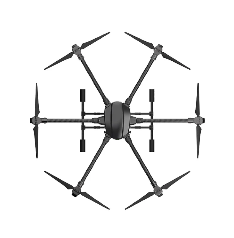
EFT 6120 Multifunction Surveillance Drone Frame
The EFT 6120 hexacopter frame is ideal for carrying LiDAR payloads. Its central payload bay accommodates the LiDAR sensor and companion computer with room for vibration-isolated mounting.

3DR 100mW Radio Telemetry 915MHz for APM/PX4/Pixhawk
Essential for real-time telemetry monitoring during autonomous LiDAR mapping missions. Monitor drone status, waypoint execution, and intervene manually if needed — without Wi-Fi dependency.
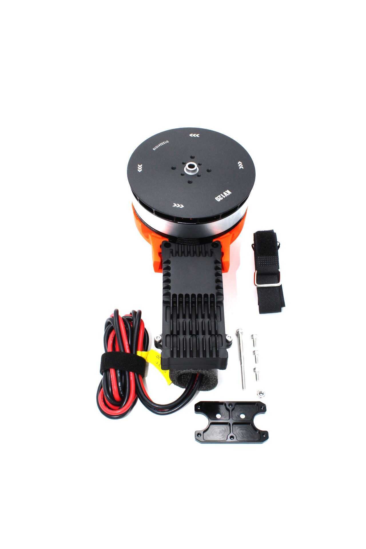
T-Motor A10-KV120-CCW Modular Propulsion System
T-Motor’s A10 series delivers the high thrust-to-weight ratio needed for heavy LiDAR payload drones. The modular design simplifies maintenance and motor replacement in the field.
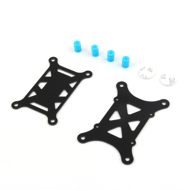
Anti-Vibration Shock Absorber for APM/KK/MWC/PixHawk
Vibration is the primary enemy of LiDAR data quality. This shock absorber isolates the flight controller from motor vibrations, improving both IMU accuracy and GNSS signal quality during mapping flights.
12. Frequently Asked Questions
What is the minimum budget for a drone LiDAR mapper in India?
A functional but limited system using an RPLIDAR A3 (2D LiDAR, not 3D), Raspberry Pi 4, and a budget hexacopter frame could be built for ₹80,000–1,20,000. This produces 2D scan slices rather than full 3D point clouds but demonstrates the complete data pipeline. A proper 3D LiDAR system with a Livox Mid-360 and Pixhawk-based drone starts at around ₹4,00,000–6,00,000 including frame, motors, ESCs, GPS, and sensor.
Do I need an RTK GPS for LiDAR mapping?
Not necessarily, but it dramatically improves absolute accuracy. Without RTK, standard GPS provides 1–3m horizontal accuracy. This means your point cloud is accurate in relative terms (internal geometry is good) but has 1–3m absolute positional error. For most terrain mapping and change detection work, this is acceptable. For engineering surveys or land boundary work, RTK GPS (providing 1–3 cm accuracy) is essential. You can also improve accuracy in post-processing using a base station and PPK (Post-Processing Kinematic) approach without needing an RTK real-time link.
Can I use ROS1 instead of ROS2?
Yes. ROS1 Noetic (last ROS1 LTS release, EOL May 2025) has more mature driver support and more community tutorials for LiDAR integration. ROS2 Humble is the future and is recommended for new projects if you can accept a steeper learning curve and occasionally less-mature package ecosystem. MAVROS is available for both ROS1 and ROS2.
How long can a LiDAR drone fly?
Flight time depends heavily on payload weight and battery capacity. A typical heavy-lift hexacopter carrying a 1–1.5kg LiDAR payload with a 6S 16,000mAh battery achieves 20–35 minutes of flight. For mapping large areas, plan for multiple battery swaps with ground-based battery charging, or use battery swap systems that allow continuous operation.
Can I get DGCA approval for commercial LiDAR surveys?
Commercial drone surveys in India require DGCA approval for drone registration and a Remote Pilot Certificate (RPC). Geospatial survey data is additionally governed by India’s Geospatial Data Guidelines 2021, which permit Indian entities to collect and use high-resolution geospatial data domestically with few restrictions. Exporting raw high-resolution geospatial data overseas may require clearance. Consult a legal expert familiar with Indian geospatial regulations for commercial deployments.
13. Conclusion and Next Steps
Building a drone LiDAR terrain mapper with ArduPilot and ROS is a complex, rewarding project that sits at the intersection of robotics, aerial systems, and geospatial technology. The open-source nature of both ArduPilot and ROS means you can learn from a global community, contribute improvements back, and build something genuinely useful for India’s growing need for affordable geospatial data collection.
Suggested progression for Indian builders:
- Master ArduPilot and Mission Planner with a basic quadcopter first
- Integrate MAVROS and learn basic ROS robotics concepts
- Add a 2D LiDAR (like RPLIDAR) for obstacle avoidance before attempting 3D mapping
- Upgrade to a 3D LiDAR sensor once you understand the data pipeline
- Add RTK GPS for survey-grade accuracy
Source Your Drone Build Components from Zbotic
Zbotic supplies professional drone frames, motors, flight controllers, telemetry modules, and more for research and commercial drone builders across India. Fast shipping, GST invoices, and technical support.


Add comment