
Table of Contents
- Introduction to BLDC Motor Control
- BLDC vs Brushed Motors: Why It Matters
- Six-Step (Trapezoidal) Commutation Theory
- Hall Effect Sensors: Reading Rotor Position
- The Commutation Table Explained
- Hardware Setup: ESC vs Custom Driver
- Arduino Six-Step Commutation Code
- Speed Control with PWM and Feedback
- Sensorless BLDC: Back-EMF Zero Crossing
- Recommended Products from Zbotic
- Frequently Asked Questions
Introduction to BLDC Motor Control
Brushless DC (BLDC) motors are everywhere in modern electronics: drones, electric vehicles, washing machines, hard disk drives, and electric bicycles all rely on their efficiency, longevity, and controllability. Yet unlike brushed DC motors that simply spin when you apply voltage, a BLDC motor requires a dedicated controller that electronically commutates the stator windings in the correct sequence to maintain rotation.
Understanding BLDC motor six-step commutation — also called trapezoidal commutation — is the foundation of all brushless motor control. Whether you are programming an ESC (Electronic Speed Controller), designing a custom motor driver PCB, or building a servo system from scratch, the six-step algorithm is where every BLDC control journey begins.
This guide takes you from first principles through to working Arduino code that reads Hall effect sensors and drives a three-phase inverter bridge through all six commutation steps. We will also cover sensorless control using back-EMF zero crossing detection — the technique used in most commercial ESCs.
BLDC vs Brushed Motors: Why It Matters
In a traditional brushed DC motor, the commutation (switching of current direction through the rotor windings) is done mechanically by carbon brushes rubbing against a copper commutator ring. This mechanical contact is the brushed motor’s greatest weakness: brushes wear out, generate electrical noise, limit maximum speed, and produce heat through friction.
A BLDC motor inverts this arrangement. The permanent magnets are on the rotor (which just spins) and the wound coils are in the stator (the stationary body). There are no brushes — commutation is done electronically by the controller. The benefits are significant:
- Longer lifespan: No brushes to wear out; bearings are the only wear item
- Higher efficiency: No brush friction losses; efficiencies of 85–95% are achievable
- Higher speed capability: No mechanical commutator speed limit
- Lower EMI: No brush arcing
- Better thermal management: Heat is generated in the stator (outside), not the rotor (inside), making it easier to dissipate
The trade-off is that BLDC motors require more complex controllers. A brushed motor needs just two wires and a voltage source. A BLDC needs three phase wires, a three-phase inverter bridge, rotor position sensing, and a commutation algorithm — this guide covers all of it.
Six-Step (Trapezoidal) Commutation Theory
A three-phase BLDC motor has three sets of stator windings: Phase A, Phase B, and Phase C. At any given moment, only two of these three phases are energised — one carrying current in, one carrying current out. The third phase is floating (disconnected).
As the rotor turns through one full electrical revolution (which may be multiple mechanical revolutions depending on the number of pole pairs), there are exactly six distinct energisation states. Each state energises a different pair of phases in a specific polarity. Cycling through these six states in the correct order causes the magnetic field in the stator to rotate, pulling the permanent magnet rotor along with it.
The six steps are:
- A+ / B− (A high, B low, C floating)
- A+ / C− (A high, C low, B floating)
- B+ / C− (B high, C low, A floating)
- B+ / A− (B high, A low, C floating)
- C+ / A− (C high, A low, B floating)
- C+ / B− (C high, B low, A floating)
The key insight is that the controller must know the rotor’s current position to select the correct step. If it energises the wrong pair, the torque produced is in the wrong direction and the motor stalls or oscillates. This is where Hall sensors come in.
Trapezoidal commutation is named after the shape of the back-EMF waveform it produces — a trapezoidal wave rather than the sinusoidal wave produced by FOC (Field-Oriented Control). This makes trapezoidal control simpler but produces slightly more torque ripple. For most applications — drones, e-bikes, fans, pumps — trapezoidal commutation is entirely adequate and far simpler to implement.
Hall Effect Sensors: Reading Rotor Position
Most sensored BLDC motors include three Hall effect sensors embedded in the stator, spaced 120° apart (electrically). As the rotor’s permanent magnets pass by, each Hall sensor outputs a HIGH or LOW signal depending on magnetic pole orientation. The combined three-bit binary reading of the three Hall sensors (H1, H2, H3) uniquely identifies one of the six rotor sectors.
Hall sensors typically have three wires: VCC (5 V), GND, and signal output. The signal is usually open-drain, requiring a 4.7 kΩ pull-up resistor to VCC. Connect the three signal wires to Arduino digital input pins with INPUT_PULLUP or external pull-ups.
Reading Hall Sensors in Arduino
const int HALL_A = 2;  // Interrupt-capable pin
const int HALL_B = 3;  // Interrupt-capable pin
const int HALL_C = 4;

byte readHallState() {
  byte state = 0;
  if (digitalRead(HALL_A)) state |= 0b001;
  if (digitalRead(HALL_B)) state |= 0b010;
  if (digitalRead(HALL_C)) state |= 0b100;
  return state; // Returns 1-6 for valid states
}
Hall sensor states 0 (000) and 7 (111) are invalid and indicate a sensor fault or wiring error. Any reading of 1–6 maps to one of the six commutation steps.
The Commutation Table Explained
The commutation table maps each Hall sensor state to the correct phase energisation pattern. This is the core lookup table that your controller firmware references every time the Hall state changes.
For a typical BLDC motor with this wiring convention (your specific motor may differ — start with this and reverse if the motor runs backwards):
| Hall State (H3H2H1) | Step | Phase A | Phase B | Phase C |
|---|---|---|---|---|
| 001 (1) | 1 | HIGH | LOW | FLOAT |
| 011 (3) | 2 | HIGH | FLOAT | LOW |
| 010 (2) | 3 | FLOAT | HIGH | LOW |
| 110 (6) | 4 | LOW | HIGH | FLOAT |
| 100 (4) | 5 | LOW | FLOAT | HIGH |
| 101 (5) | 6 | FLOAT | LOW | HIGH |
In the H-bridge drive circuit, HIGH means the high-side FET is on (phase connected to supply), LOW means the low-side FET is on (phase connected to GND), and FLOAT means both FETs are off (phase disconnected/floating).
Hardware Setup: ESC vs Custom Driver
For most hobbyist BLDC applications, using a commercial ESC (Electronic Speed Controller) is the right choice. ESCs handle all the gate driving, dead-time insertion, protection, and commutation logic internally. You control them via a standard RC PWM signal (1000–2000 µs pulse width) from the Arduino.
For the 30A BLDC ESC available at Zbotic:
- Connect the three motor wires (A, B, C) to the ESC’s output wires. If the motor spins the wrong direction, swap any two wires.
- Connect the ESC’s signal wire (usually white or orange) to an Arduino PWM pin.
- Power the ESC from your battery (typically 3S–4S LiPo for drone motors).
- The ESC’s BEC (Battery Eliminator Circuit) supplies 5 V to power the Arduino from the same battery.
ESC Calibration
Most ESCs require calibration on first use to learn the throttle range:
- Send maximum throttle signal (2000 µs) while powering on the ESC.
- Wait for calibration beep sequence.
- Send minimum throttle (1000 µs) and wait for completion beeps.
- The ESC now knows your full throttle range.
Arduino Six-Step Commutation Code
This example implements six-step commutation for a custom gate driver (e.g., IR2103 half-bridge drivers). It reads Hall sensors on interrupt pins and immediately updates the drive pattern for minimum commutation delay:
// Six-step BLDC commutation for Arduino
// Requires: 6 PWM outputs for 3-phase half-bridge
// AH, AL = Phase A high/low gate
// BH, BL = Phase B high/low gate
// CH, CL = Phase C high/low gate

#define AH 3
#define AL 4
#define BH 5
#define BL 6
#define CH 9
#define CL 10
#define HALL_A 2
#define HALL_B 7
#define HALL_C 8

int pwmDuty = 128; // 0-255 speed

void allOff() {
  digitalWrite(AH, LOW); digitalWrite(AL, LOW);
  digitalWrite(BH, LOW); digitalWrite(BL, LOW);
  digitalWrite(CH, LOW); digitalWrite(CL, LOW);
}

void setStep(byte step) {
  allOff();
  switch(step) {
    case 1: analogWrite(AH, pwmDuty); digitalWrite(BL, HIGH); break;
    case 2: analogWrite(AH, pwmDuty); digitalWrite(CL, HIGH); break;
    case 3: analogWrite(BH, pwmDuty); digitalWrite(CL, HIGH); break;
    case 4: analogWrite(BH, pwmDuty); digitalWrite(AL, HIGH); break;
    case 5: analogWrite(CH, pwmDuty); digitalWrite(AL, HIGH); break;
    case 6: analogWrite(CH, pwmDuty); digitalWrite(BL, HIGH); break;
  }
}

byte getCommutationStep() {
  byte hall = 0;
  if (digitalRead(HALL_A)) hall |= 1;
  if (digitalRead(HALL_B)) hall |= 2;
  if (digitalRead(HALL_C)) hall |= 4;
  // Map Hall state to commutation step
  const byte hallToStep[] = {0, 1, 3, 2, 5, 6, 4, 0};
  return hallToStep[hall];
}

void setup() {
  pinMode(AH, OUTPUT); pinMode(AL, OUTPUT);
  pinMode(BH, OUTPUT); pinMode(BL, OUTPUT);
  pinMode(CH, OUTPUT); pinMode(CL, OUTPUT);
  pinMode(HALL_A, INPUT_PULLUP);
  pinMode(HALL_B, INPUT_PULLUP);
  pinMode(HALL_C, INPUT_PULLUP);
  allOff();
}

void loop() {
  byte step = getCommutationStep();
  if (step != 0) setStep(step);
  // Adjust pwmDuty here based on speed reference
}
Important note on dead time: In a real implementation, you must insert a dead time (typically 1–5 µs) between turning off one FET and turning on the complementary FET to prevent shoot-through (both high-side and low-side FETs on simultaneously = short circuit). The code above does not include dead time — use a dedicated gate driver IC like IR2103, IR2183, or DRV8302 that has configurable dead time built in.
Speed Control with PWM and Feedback
Speed control in six-step commutation is achieved by varying the PWM duty cycle applied to the active high-side gate. Lower duty cycle = lower average voltage = lower speed. This is the variable pwmDuty in the code above.
For open-loop speed control, simply change pwmDuty in response to a potentiometer or serial command. For closed-loop speed control, measure actual speed by counting Hall sensor transitions:
volatile unsigned long lastHallTime = 0;
volatile unsigned long hallPeriod = 0;

void hallISR() {
  unsigned long now = micros();
  hallPeriod = now - lastHallTime;
  lastHallTime = now;
  // Also update commutation here for fastest response
  byte step = getCommutationStep();
  if (step != 0) setStep(step);
}

float getRPM(int polePairs) {
  if (hallPeriod == 0) return 0;
  // 6 Hall transitions per electrical revolution
  // polePairs electrical revolutions per mechanical revolution
  return 60000000.0 / (hallPeriod * 6.0 * polePairs);
}
Attach this ISR to the Hall sensor interrupt pins and use the resulting RPM reading in a PID controller to adjust pwmDuty and maintain constant speed under varying load.
Sensorless BLDC: Back-EMF Zero Crossing
High-volume BLDC applications (fans, power tools, many ESCs) use sensorless commutation to eliminate the Hall sensor wires, reducing cost and improving reliability. Instead of Hall sensors, the controller monitors the back-EMF (voltage induced by the spinning magnets) on the floating phase.
In each commutation step, one phase is floating. As the rotor spins, the magnets induce a sinusoidal voltage on this floating winding. This back-EMF crosses the motor’s neutral point (half of supply voltage) exactly at the moment when the next commutation step should occur. This event is called the zero-crossing.
Detecting back-EMF zero crossings requires:
- A voltage divider on each phase to bring the back-EMF into the ADC’s input range (0–5 V)
- Fast ADC sampling or a comparator to detect the zero-crossing moment
- A commutation delay (typically 30° electrical) after zero-crossing before advancing the step
- A startup sequence (forced commutation at low speed) since back-EMF is too small to detect at standstill
Sensorless BLDC is significantly more complex to implement reliably, particularly at low speeds and under rapidly changing loads. For most hobbyist projects, use sensored motors or a pre-built ESC that handles sensorless control internally.
Recommended Products from Zbotic
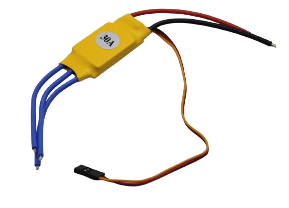
30A BLDC ESC Brushless Electronic Speed Controller
A ready-to-use 30 A ESC implementing sensorless six-step commutation internally. Simply connect your BLDC motor and control via RC PWM signal from Arduino — no commutation coding required.

2204 260KV Brushless Gimbal Motor (30cm Cable)
A sensored 2204 gimbal motor with Hall effect sensors — ideal for learning six-step commutation at low speed where sensorless back-EMF detection is unreliable.
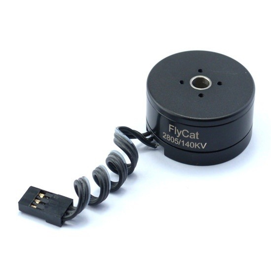
2805 140KV Gimbal Brushless Motor
Low KV, high pole count gimbal motor perfect for hands-on BLDC commutation study. Its low speed and high torque characteristics make Hall sensor timing errors immediately visible.
Frequently Asked Questions
What is the difference between six-step commutation and FOC (Field-Oriented Control)?
Six-step (trapezoidal) commutation energises two phases at a time and produces a stepped magnetic field rotation with inherent torque ripple at each commutation event. FOC controls all three phases simultaneously with sinusoidal currents, creating a smoothly rotating magnetic field with minimal torque ripple. FOC requires more computational power (typically a DSP or ARM Cortex-M) and Clarke/Park transforms, while six-step runs on an AVR Arduino. FOC is preferred for servo applications; six-step is preferred for high-speed applications like drones and e-bikes.
My motor hums but does not spin. What is wrong?
This usually means the commutation sequence is incorrect or the Hall sensor mapping is wrong. The motor energises one step repeatedly instead of advancing through the sequence. Check: (1) the Hall sensor connections match your commutation table, (2) the motor spins freely by hand in the expected direction, (3) the commutation table polarity is correct for your motor’s winding direction.
How do I find the number of pole pairs in my BLDC motor?
Count the magnets visible on the rotor (if the motor is open) and divide by 2. For outrunner motors with the rotor on the outside, you can also count the bump-click positions when you slowly spin the motor shaft by hand — each position is one electrical step. Total positions divided by 6 = number of pole pairs.
Can I use the Arduino Nano for six-step commutation?
Yes. The Arduino Nano has the same AVR core as the Uno. However, its interrupt-capable pins are limited to D2 and D3. For Hall sensors, you can read the other pins in the commutation ISR (triggered by D2/D3) without significant delay.
What causes motor overheating during six-step commutation?
Common causes: (1) stalling the motor at high duty cycle, (2) wrong commutation timing causing negative torque briefly at each step, (3) running at too low a speed for too long at high duty cycle. Always implement overcurrent protection and thermal monitoring.
Start Your BLDC Control Journey
From gimbal stabilisation to electric vehicle drives, mastering BLDC commutation opens the door to the most powerful and efficient motors available to hobbyists. Find BLDC motors, ESCs, and control boards at Zbotic to kickstart your project.


Add comment