
An Arduino SCARA robot for pick and place automation is one of the most satisfying DIY projects for any electronics or robotics enthusiast. SCARA (Selective Compliance Assembly Robot Arm) robots are used extensively in industrial automation — and now, thanks to accessible servo motors, acrylic frames, and Arduino microcontrollers, you can build a functional desktop version at home. This guide takes you from concept to a working pick-and-place arm.
What Is a SCARA Robot and Why Build One?
A SCARA robot has two revolute joints in the horizontal plane (giving X-Y motion) and one prismatic joint for vertical (Z-axis) motion. Unlike a 6-DOF articulated arm, SCARA robots are fast, stiff in the vertical direction, and excellent at repetitive horizontal positioning tasks — exactly what pick-and-place needs.
Key advantages of a SCARA design:
- High repeatability: Two joints in the same plane means fewer error accumulation axes.
- Fast horizontal movement: Lightweight arms allow rapid sweeping motions.
- Ideal for flat surfaces: Sorting, packing, assembly-line simulation, PCB component placing.
- Simpler kinematics: 2D inverse kinematics is solvable analytically — no numerical solvers needed.
For an Arduino-based build, the arm typically uses 3–4 servo motors: two for the horizontal SCARA joints, one for Z-axis lift (linear slider or rack-and-pinion), and one small servo as the end-effector gripper.
Hardware Components List
Here’s everything you need for a complete desktop SCARA robot build:
- Arduino Mega 2560 (more PWM pins than Uno — essential for 4+ servos)
- 3× MG996R high-torque servo (shoulder, elbow, Z-axis)
- 1× SG90 micro servo (gripper)
- Acrylic or 3D-printed arm links (150mm and 120mm length)
- Servo mount brackets (pair for each joint)
- Bearing or bronze bushing for pivot points
- M3 screws, nuts, and standoffs
- 5V 3A power supply (dedicated servo power — NOT Arduino 5V pin)
- Servo shield or breadboard for power distribution
- Suction cup + mini vacuum pump or small gripper claw as end-effector

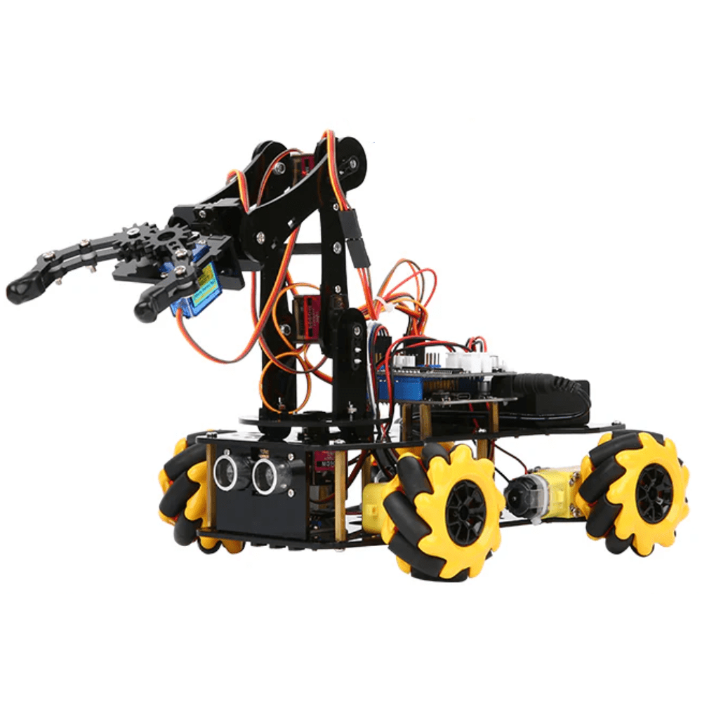
DIY Acrylic Robot Manipulator Mechanical Arm Kit
A complete acrylic arm frame kit — save hours of cutting and drilling with precision laser-cut acrylic links and mounting plates ready for servo installation.
ACEBOTT ESP32 5-DOF Robot Arm Kit Expansion Pack – QD007
A ready-to-expand 5-DOF arm kit with ESP32 control — excellent reference design for understanding servo-based arm kinematics before building your custom SCARA.
Mechanical Assembly Guide
Mechanical precision determines how repeatable your SCARA robot will be. Follow these steps carefully:
- Base plate: Mount the shoulder servo horizontally using a servo horn screwed to the base plate. The servo body is fixed; the horn drives arm link 1.
- Link 1 (upper arm): Attach a 150mm acrylic piece to the shoulder servo horn. At the far end, mount the elbow servo with its body fixed to link 1 and horn driving link 2.
- Link 2 (forearm): A 120mm acrylic piece mounted to the elbow servo horn. The ratio 150:120 gives a good workspace without singularity issues.
- Z-axis: Use a vertical linear rail or rack-and-pinion driven by an MG996R servo or NEMA17 stepper for vertical pick/place movement.
- End-effector: Mount an SG90 servo driving a small gripper jaw, or attach a 5V mini vacuum pump for suction cup operation.
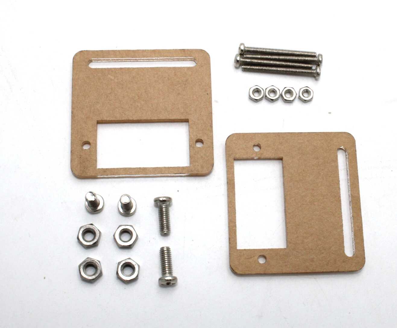
Servo Mount Holder Bracket for SG90/MG90 (Pack of 2)
Rigid aluminium servo brackets for clean, reliable servo-to-frame mounting at each joint of your SCARA arm. Eliminates flex that ruins repeatability.
Wiring the Electronics
This is where beginners often damage servos. Never power servos from the Arduino’s 5V pin — it can only source ~500mA, while three MG996R servos at load can draw 3–4A combined. Use a separate 5V 3A regulated supply.
Wiring summary:
- Servo signal wires → Arduino Mega PWM pins (2, 3, 4, 5)
- Servo power (red) → external 5V supply positive
- Servo ground (black/brown) → external 5V supply negative AND Arduino GND (shared ground is essential)
- Arduino powered via USB or separate 12V barrel jack → Vin pin
Use a capacitor (470µF, 6.3V) across the servo power rails to smooth voltage spikes when motors start. This prevents the Arduino from resetting mid-operation.
Understanding Inverse Kinematics for SCARA
Inverse kinematics (IK) converts a target (x, y) coordinate in the robot’s workspace into joint angles (θ1, θ2) for the shoulder and elbow servos. For a 2-link planar arm with link lengths L1 and L2:
// L1 = 150mm (upper arm), L2 = 120mm (forearm)
float L1 = 150.0, L2 = 120.0;

void inverseKinematics(float x, float y, float &theta1, float &theta2) {
  float d = sqrt(x*x + y*y);
  // Clamp d to reachable workspace
  d = constrain(d, abs(L1-L2)+1, L1+L2-1);

  float cosT2 = (x*x + y*y - L1*L1 - L2*L2) / (2*L1*L2);
  theta2 = acos(cosT2);                         // elbow angle (radians)

  float k1 = L1 + L2*cos(theta2);
  float k2 = L2*sin(theta2);
  theta1 = atan2(y, x) - atan2(k2, k1);        // shoulder angle (radians)

  theta1 = degrees(theta1);
  theta2 = degrees(theta2);
}
There are two solutions (elbow-up and elbow-down) — choose elbow-down for most table-top applications by using the positive root for θ2.
Arduino Code: Pick and Place Control
The full sketch below moves the arm between two programmed positions (pick and place) in a loop. Adapt the coordinates to your specific workspace:
#include <Servo.h>
#include <math.h>

Servo shoulder, elbow, zAxis, gripper;
const float L1=150.0, L2=120.0;

void setup() {
  shoulder.attach(2); elbow.attach(3);
  zAxis.attach(4);    gripper.attach(5);
  moveTo(200, 0, 50);   // home position
  delay(1000);
}

void loop() {
  // Pick sequence
  moveTo(180, 80, 50);   // move above pick
  delay(500);
  zAxis.write(120);       // lower Z
  delay(600);
  gripper.write(30);      // close gripper
  delay(400);
  zAxis.write(50);        // raise Z
  delay(600);
  // Place sequence
  moveTo(-150, 120, 50); // move above place
  delay(500);
  zAxis.write(120);       // lower Z
  delay(600);
  gripper.write(90);      // open gripper
  delay(400);
  zAxis.write(50);        // raise Z
  delay(800);
}

void moveTo(float x, float y, int zDeg) {
  float t1, t2;
  inverseKinematics(x, y, t1, t2);
  // Map joint angles to servo positions (calibrate offsets!)
  shoulder.write(90 + t1);
  elbow.write(90 - t2);
  zAxis.write(zDeg);
  delay(300);
}

void inverseKinematics(float x, float y, float &t1, float &t2) {
  float cosT2 = (x*x+y*y-L1*L1-L2*L2)/(2*L1*L2);
  cosT2 = constrain(cosT2,-1,1);
  t2 = degrees(acos(cosT2));
  float k1=L1+L2*cos(radians(t2)), k2=L2*sin(radians(t2));
  t1 = degrees(atan2(y,x)-atan2(k2,k1));
}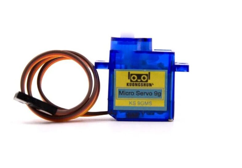
Servo SG90 9g 180 Degree
Lightweight and precise SG90 servo — ideal for the gripper jaw of your SCARA robot where low weight at the end-effector reduces arm load and vibration.
Calibration and Tuning
Even perfect code produces a poor robot without calibration. These steps get your SCARA arm working repeatably:
- Find servo zero offsets: Command each servo to 90° and mark the actual physical angle. Add or subtract this offset in your
moveTo()function. - Measure arm links precisely: Even 2mm errors in L1 or L2 will shift the tip position by several millimetres at full extension.
- Set movement speed: Replace instant
servo.write()with a sweep loop that increments angle by 1° with a small delay. Prevents mechanical shock. - Workspace test: Draw the theoretical workspace on paper (annulus between L1−L2 and L1+L2 radius). Verify the robot tip touches expected points.
- Gripper calibration: Determine the exact open and close angles for your gripper servo to grip firmly without stripping gears.
Project Extensions and Upgrades
Once your basic SCARA is working, try these upgrades:
- Computer vision picking: Add a Raspberry Pi with camera above the workspace. Use OpenCV to detect object positions and send coordinates to Arduino via serial.
- Stepper Z-axis: Replace the Z-axis servo with a NEMA17 stepper for precise, repeatable vertical motion with position feedback.
- G-code interface: Add GRBL-compatible firmware so the arm can be controlled from Candle or any G-code sender.
- Conveyor integration: Add an IR sensor on a small conveyor belt so the arm picks objects only when an item is detected.
- Multiple pick points: Implement a lookup table of pick coordinates for sorting coloured objects detected by colour sensor.
Frequently Asked Questions
- What is the difference between SCARA and a 6-DOF robot arm?
- A SCARA robot has 3–4 degrees of freedom optimised for horizontal movement — it’s faster and more rigid for planar pick-and-place. A 6-DOF arm has full spatial freedom but is more complex mechanically and computationally.
- Can I use stepper motors instead of servos for SCARA?
- Yes, steppers with encoders (closed-loop) give much better repeatability. Use A4988 or TMC2209 drivers. However, servos are easier to program for a first build.
- What payload can a servo-based SCARA robot carry?
- With MG996R servos at shoulder and elbow, expect a practical payload of 50–150g at the tip. Heavier loads require geared stepper motors or larger digital servos (like DS3225).
- How do I control the SCARA from a PC?
- Send X, Y, Z coordinates over Arduino serial port from a Python script using pyserial. Parse in Arduino
loop()withSerial.parseInt()and callmoveTo(). - What is a singularity and how do I avoid it?
- A singularity occurs when both arm links are fully extended (d = L1+L2) or fully folded (d = |L1−L2|). The IK solution becomes undefined. Add boundary checks in your
inverseKinematics()to constrain the target within a safe radius.
Start Your SCARA Build Today
Find servo motors, arm kits, stepper drivers, and all the components you need for your pick-and-place robot at Zbotic.


Add comment