
If you’ve ever wondered why your DIY drone wobbles, flips, or crashes moments after lift-off, the answer almost always lies in drone stabilisation. Understanding MPU6050 and PID control explained in simple terms is the key to building a drone that actually flies steady. In this guide, we’ll walk through the full stabilisation loop — from reading raw IMU data with the MPU6050 to implementing and tuning a PID controller that keeps your quad locked in the air.
What Is Drone Stabilisation?
Drone stabilisation is the process of continuously measuring a drone’s orientation — roll, pitch, and yaw — and adjusting motor speeds to maintain the desired attitude. Without it, any small disturbance (wind gust, motor imbalance, weight offset) would cause uncontrolled rotation.
Modern flight controllers achieve stabilisation by running a high-frequency control loop, typically 250–1000 Hz, that reads an Inertial Measurement Unit (IMU), calculates the error from the target orientation, and sends corrected signals to the ESCs controlling each motor.
For DIY builders, the MPU6050 is the most popular IMU because it combines a 3-axis gyroscope and 3-axis accelerometer in a single I²C chip — and it costs under ₹100. Pair it with an Arduino or ESP32 and a PID algorithm, and you have the foundation of a working flight controller.
MPU6050 IMU: Accelerometer + Gyroscope
The MPU6050 from InvenSense is a 6-axis MotionTracking device. Here’s what each sensor does in the context of drone flight:
- Gyroscope: Measures angular velocity (degrees per second) around each axis. Excellent for detecting fast rotations but drifts over time due to integration error.
- Accelerometer: Measures linear acceleration including gravity. Can calculate absolute tilt angles but is noisy and sensitive to vibration — a major problem on a drone frame.
The solution is a complementary filter or a Kalman filter that fuses both sensors: the gyroscope handles fast, accurate short-term rotation data, and the accelerometer corrects long-term drift.
Key MPU6050 specs:
- Gyro range: ±250 / ±500 / ±1000 / ±2000 °/s (configurable)
- Accel range: ±2g / ±4g / ±8g / ±16g (configurable)
- Interface: I²C (address 0x68 or 0x69)
- Built-in Digital Motion Processor (DMP) for onboard fusion
- Operating voltage: 2.375V–3.46V (most breakout boards include a 3.3V regulator)
Wiring the MPU6050 to Arduino
The MPU6050 connects over I²C, so you only need 4 wires plus power:
| MPU6050 Pin | Arduino Uno/Nano Pin |
|---|---|
| VCC | 3.3V |
| GND | GND |
| SDA | A4 |
| SCL | A5 |
| AD0 | GND (address 0x68) |
| INT | D2 (optional interrupt) |
Important mounting note: Mount the MPU6050 flat on the drone frame with the X-axis pointing forward. Use soft foam or silicone grommets to dampen motor vibrations — vibration is the number-one enemy of IMU accuracy on a drone.
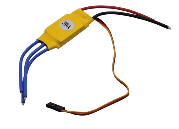
30A BLDC ESC Brushless Electronic Speed Controller
Essential for translating PID output into motor thrust. This 30A ESC handles most 5-inch to 7-inch drone builds with ease.
Reading and Filtering Sensor Data
Install the Wire library (built-in) and the MPU6050 library by Electronic Cats or Jeff Rowberg. Here’s a minimal snippet to read raw gyro and accel data:
#include <Wire.h>
#include <MPU6050.h>

MPU6050 mpu;

void setup() {
  Wire.begin();
  mpu.initialize();
  mpu.setFullScaleGyroRange(MPU6050_GYRO_FS_500); // 500 dps
  mpu.setFullScaleAccelRange(MPU6050_ACCEL_FS_4); // ±4g
}

void loop() {
  int16_t ax, ay, az, gx, gy, gz;
  mpu.getMotion6(&ax, &ay, &az, &gx, &gy, &gz);

  // Convert to physical units
  float gyroX = gx / 65.5; // degrees/sec at 500 dps range
  float accelZ = az / 8192.0; // g at ±4g range
}
Complementary Filter for Angle Estimation
The most lightweight fusion approach for flight controllers is the complementary filter. It trusts the gyro for fast changes and the accelerometer for slow drift correction:
float alpha = 0.98; // trust 98% gyro, 2% accel
float dt = 0.004;   // 4ms loop time (250Hz)

float angleAccel = atan2(ay, az) * 180.0 / PI;
angle = alpha * (angle + gyroX * dt) + (1 - alpha) * angleAccel;
For better performance, especially in vibration-heavy environments, consider a Madgwick or Mahony filter from the MadgwickAHRS Arduino library.
PID Control Basics: P, I, and D Explained
PID stands for Proportional, Integral, and Derivative. The PID controller’s job is to calculate how much motor correction is needed based on the difference between where the drone is and where you want it to be (the error).
Proportional (P)
The P term produces an output proportional to the current error. If the drone is tilted 10° and your P gain is 2.0, the correction signal is 20. P is the main driving force — too low and the drone responds sluggishly; too high and it oscillates.
Integral (I)
The I term accumulates error over time. It corrects for steady-state errors — for example, if one motor is slightly weaker, the drone will permanently drift without I correction. However, excessive I causes integral windup, making the drone wander and overshoot.
Derivative (D)
The D term reacts to the rate of change of error. It acts as a brake, damping oscillations caused by a high P gain. Think of it as predictive correction. D is very sensitive to sensor noise, so always low-pass filter your derivative input.
PID output formula:
error = setpoint - measured_angle;
integral += error * dt;
derivative = (error - prev_error) / dt;

output = Kp * error + Ki * integral + Kd * derivative;
prev_error = error;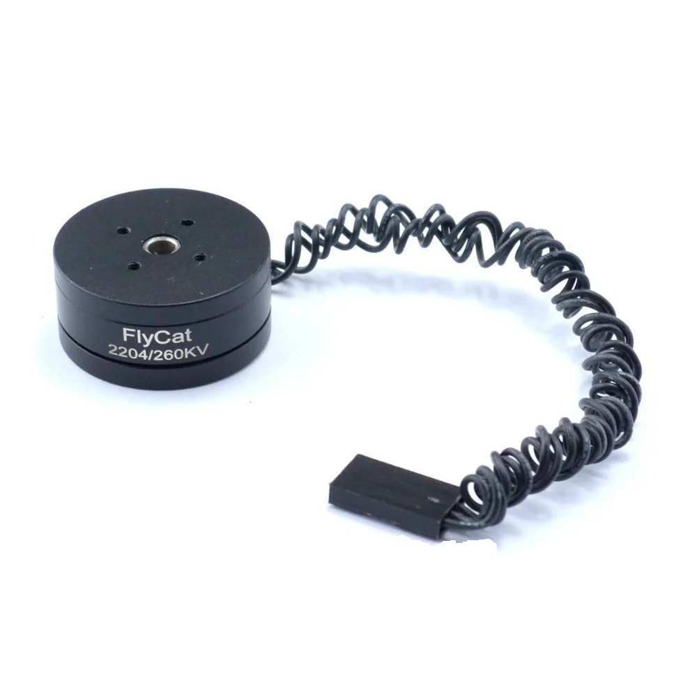
2204 260KV Brushless Gimbal Motor
Perfect for gimbal and light drone builds. Low KV brushless motor delivers smooth, controllable thrust ideal for PID tuning experiments.
How to Tune PID Gains for Your Drone
PID tuning is part science, part art. Start with all three gains at zero, then increase P until the drone oscillates, then back off 20–30%. Add D to dampen the oscillation. Finally, add a small I to fix drift. Here’s a structured approach:
Step 1: Set Initial Values
Start conservative: Kp = 1.0, Ki = 0.0, Kd = 0.0. Secure the drone on a test jig or hold it by a string so it can rotate on one axis but can’t fly away.
Step 2: Tune Roll and Pitch P
Increase Kp in steps of 0.5. You’re looking for the drone to snap back to level when displaced. If it oscillates rapidly, you’ve gone too high. Back off until oscillation just stops, then reduce by 30%.
Step 3: Add Derivative D
Increase Kd until the oscillations from a high Kp are damped without making the drone feel mushy. Typical range: 0.01–0.1 depending on your loop frequency.
Step 4: Add Integral I
Start very small: Ki = 0.01. Let the drone hover and watch for slow drift. Increase until drift is eliminated. Cap integral windup by clamping the integral sum to a maximum value.
Yaw Tuning
Yaw is driven by torque difference between CW and CCW motors and typically needs a much lower P gain (0.3–0.8). Yaw rarely needs an integral term unless your motors are significantly mismatched.
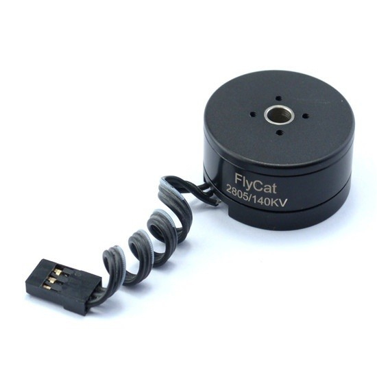
2805 140KV Gimbal Brushless Motor
A heavy-duty gimbal brushless motor with excellent torque at low speeds — ideal for stabilisation rigs and camera gimbal projects.
Putting It All Together: The Flight Control Loop
A complete flight controller loop runs as follows at 250Hz (every 4ms):
- Read IMU: Get raw gyro and accel values from MPU6050 via I²C.
- Fuse angles: Apply complementary filter to get roll, pitch, yaw angles.
- Read RC input: Decode PWM or SBUS from the receiver for pilot setpoints.
- Calculate error:
error = setpoint_angle - current_anglefor roll and pitch;error = setpoint_rate - gyro_ratefor yaw (rate mode). - Run PID: Compute P, I, D correction for each axis.
- Mix motors: Combine throttle + roll PID + pitch PID + yaw PID into 4 individual motor commands.
- Output ESC signals: Write PWM values (1000–2000µs) to each ESC via
servo.writeMicroseconds()or direct timer registers.
Motor mixing for a standard X-quad configuration:
// Front-Left, Front-Right, Rear-Left, Rear-Right
motor[0] = throttle + rollPID - pitchPID - yawPID; // FL (CCW)
motor[1] = throttle - rollPID - pitchPID + yawPID; // FR (CW)
motor[2] = throttle + rollPID + pitchPID + yawPID; // RL (CW)
motor[3] = throttle - rollPID + pitchPID - yawPID; // RR (CCW)

// Clamp to valid ESC range
for (int i = 0; i < 4; i++) motor[i] = constrain(motor[i], 1000, 2000);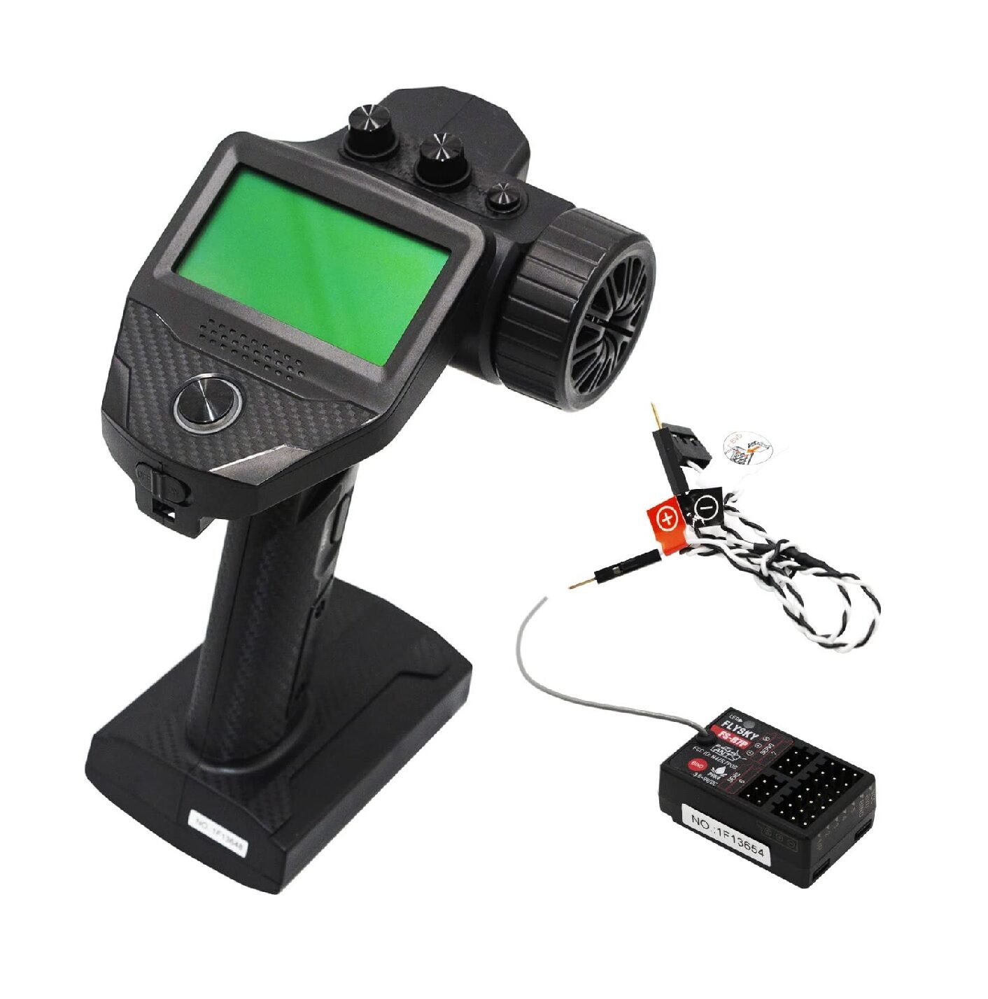
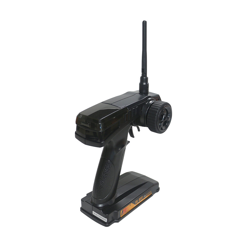
Flysky FS-G7P 2.4GHz ANT Transmitter with FS-R7P Receiver
Reliable 2.4GHz RC system for drone control. 7 channels with ANT protocol — great for DIY drone PID testing and flying.
Common Mistakes and How to Fix Them
- Motor vibration corrupting IMU: Always mount the MPU6050 on vibration-damping foam. Even a thin piece of foam tape helps significantly.
- I²C running too slow: Default Arduino I²C speed is 100kHz. Set it to 400kHz with
Wire.setClock(400000)to keep up with a 250Hz loop. - Integral windup causing oscillation: Add anti-windup clamping — limit
integralto ±200 or reset it when throttle is below arming threshold. - Not accounting for ESC dead-band: Most ESCs need at least 1100µs before they spin. Map your throttle accordingly.
- Wrong motor direction: Verify each motor spins in the correct direction for your frame layout BEFORE running PID. Swap any two ESC wires to reverse a motor.
- PID running at inconsistent rate: Use hardware timers or
micros()to maintain a fixed dt. If dt varies, your derivative term will be noisy and your integral inaccurate.
Recommended Products from Zbotic
Flysky FS-GT2 Transmitter with FS-GR3E Receiver
Entry-level 2.4GHz RC transmitter and receiver combo — ideal for early drone experiments and ground testing of your PID controller.
Frequently Asked Questions
Can I use an Arduino Uno as a drone flight controller?
Yes, an Arduino Uno can run a basic PID flight controller with the MPU6050, but it has limited processing power. For a 250Hz loop with 4 ESC outputs, it works — but for more advanced features like telemetry or GPS, consider an Arduino Mega or STM32-based board.
What is the difference between rate mode and angle mode PID?
In angle mode (self-levelling), the PID setpoint is an angle (e.g., 0° = level). In rate mode (acro), the setpoint is a rotation rate in degrees per second. Rate mode is used by freestyle and racing pilots for full manual control. Angle mode is easier for beginners.
Why does my drone oscillate even after PID tuning?
Oscillation after tuning usually means your P gain is still too high, or motor vibration is feeding noise into the derivative term. Try reducing Kp by 20% and add a low-pass filter on your gyro derivative input. Also check motor balance and propeller balance.
Do I need a barometer for drone stabilisation?
Not for basic attitude stabilisation. Roll and pitch stabilisation only needs the gyro and accelerometer. A barometer (like BMP280) is needed for altitude hold, and a GPS is needed for position hold. The MPU6050 alone is sufficient for stable attitude control.
What MPU6050 library should I use for Arduino?
The most popular choices are Jeff Rowberg’s i2cdevlib MPU6050 library (full-featured with DMP support) and the Electronic Cats MPU6050 library. For raw sensor reading without DMP, either works. For DMP-based quaternion fusion, use Jeff Rowberg’s version.
Ready to Build Your Own Stable Drone?
Zbotic stocks all the components you need — ESCs, brushless motors, and RC systems — to take your drone from wobbly prototype to locked-in flier. Explore our Robotics & DIY range for motors, ESCs, chassis kits, and more delivered across India.


Add comment