
Build a Wireless Weather Station with NRF24L01 & Arduino
Building a wireless weather station NRF24L01 Arduino project is one of the most satisfying weekend maker builds — it combines environmental sensing, wireless communication, and real-time data display into a practical device you can actually use. In this complete guide, you will build a two-node weather monitoring system: one outdoor sensor node that reads temperature, humidity, and atmospheric pressure, and one indoor display station that receives the data wirelessly over NRF24L01 and shows it on an OLED screen. Let us get started!
Project Overview and Features
This wireless weather station consists of two Arduino-based nodes:
Outdoor Sensor Node:
- DHT22 sensor for temperature and humidity
- BMP280 sensor for barometric pressure and altitude
- NRF24L01 module for wireless data transmission
- Arduino Nano (small form factor, 3.3V/5V compatible)
- Battery-powered with sleep mode for energy efficiency
Indoor Display Station:
- NRF24L01 module to receive data
- 0.96″ OLED display showing all sensor readings
- Arduino Uno or Nano as the hub
- USB powered from any phone charger
The system transmits sensor data every 30 seconds. The outdoor node enters low-power sleep between transmissions, extending battery life significantly. All readings are displayed in real time on the OLED with automatic screen updates.
Full Components List
| Component | Qty | Notes |
|---|---|---|
| Arduino Nano | 2 | One per node |
| NRF24L01 module | 2 | Standard or PA+LNA version |
| DHT22 sensor | 1 | For outdoor node |
| BMP280 module | 1 | Pressure + altitude |
| 0.96″ OLED I2C display | 1 | SSD1306 chip |
| 100 µF capacitor | 2 | NRF24L01 power stabilisation |
| 3.3V LDO regulator (AMS1117) | 1 | Dedicated 3.3V for outdoor NRF24L01 |
| 18650 battery + holder | 1 | Outdoor node power |
| Jumper wires, breadboard | — |

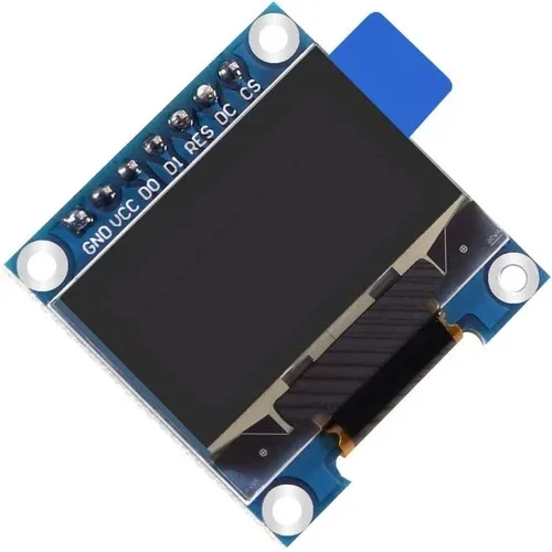
0.96 Inch I2C OLED LCD Module (White SSD1306)
Perfect for the weather station display node. This white SSD1306 OLED shows crisp text and graphics with just 2 wires (SDA/SCL), leaving plenty of pins free for other functions.
Outdoor Sensor Node: Wiring Guide
Connect the outdoor sensor node components to Arduino Nano as follows:
NRF24L01 to Arduino Nano:
- VCC → 3.3V (use external AMS1117 regulator, not Nano’s onboard 3.3V)
- GND → GND
- CE → D9, CSN → D10, SCK → D13, MOSI → D11, MISO → D12
DHT22 to Arduino Nano:
- VCC → 5V, GND → GND, DATA → D2
- Add 10 kΩ pull-up resistor between DATA and VCC
BMP280 to Arduino Nano (I2C):
- VCC → 3.3V, GND → GND, SDA → A4, SCL → A5
Power: Connect 18650 battery (3.7V nominal) through an AMS1117-5V regulator to Nano’s VIN pin. A separate AMS1117-3.3V powers the NRF24L01 and BMP280.
Indoor Display Station: Wiring Guide
NRF24L01 to Arduino (same SPI wiring as outdoor node)
OLED (SSD1306 I2C) to Arduino: SDA → A4, SCL → A5, VCC → 3.3V, GND → GND
Sensor Node Arduino Code
Install these libraries before compiling: RF24 (TMRh20), DHT sensor library (Adafruit), Adafruit BMP280.
#include <SPI.h>
#include <RF24.h>
#include <DHT.h>
#include <Adafruit_BMP280.h>
#include <avr/sleep.h>
#include <avr/wdt.h>

#define DHTPIN 2
#define DHTTYPE DHT22

RF24 radio(9, 10);
DHT dht(DHTPIN, DHTTYPE);
Adafruit_BMP280 bmp;

const uint64_t txPipe = 0xF0F0F0F0E1LL;

struct WeatherData {
  float temperature;   // from DHT22
  float humidity;      // from DHT22
  float pressure;      // from BMP280 (hPa)
  float altitude;      // from BMP280 (metres)
  float heatIndex;     // computed
  uint32_t readingID;
};

uint32_t readingCounter = 0;

void setup() {
  Serial.begin(9600);
  dht.begin();
  if (!bmp.begin(0x76)) {
    Serial.println("BMP280 not found! Check wiring.");
  }
  bmp.setSampling(Adafruit_BMP280::MODE_FORCED,
                  Adafruit_BMP280::SAMPLING_X2,
                  Adafruit_BMP280::SAMPLING_X16,
                  Adafruit_BMP280::FILTER_X16,
                  Adafruit_BMP280::STANDBY_MS_500);

  radio.begin();
  radio.setPALevel(RF24_PA_LOW);
  radio.setDataRate(RF24_250KBPS);
  radio.setChannel(108);
  radio.openWritingPipe(txPipe);
  radio.stopListening();
  Serial.println("Sensor node ready");
}

void loop() {
  delay(2000); // DHT22 needs 2s between readings

  WeatherData data;
  data.temperature = dht.readTemperature();
  data.humidity    = dht.readHumidity();
  data.pressure    = bmp.readPressure() / 100.0F; // convert Pa to hPa
  data.altitude    = bmp.readAltitude(1013.25);   // sea level pressure
  data.heatIndex   = dht.computeHeatIndex(data.temperature, data.humidity, false);
  data.readingID   = ++readingCounter;

  if (isnan(data.temperature) || isnan(data.humidity)) {
    Serial.println("DHT22 read failed!");
    return;
  }

  bool success = radio.write(&data, sizeof(data));
  Serial.print("Sent reading #");
  Serial.print(data.readingID);
  Serial.print(" Temp:");
  Serial.print(data.temperature);
  Serial.print(" Hum:");
  Serial.print(data.humidity);
  Serial.print(" Press:");
  Serial.print(data.pressure);
  Serial.println(success ? " [OK]" : " [FAIL]");

  // Sleep for ~28 seconds (8s WDT x 3 + 4s = ~28s + 2s DHT delay = 30s total)
  for (int i = 0; i < 3; i++) {
    set_sleep_mode(SLEEP_MODE_PWR_DOWN);
    sleep_enable();
    wdt_enable(WDTO_8S);
    sleep_mode();
    sleep_disable();
  }
  delay(4000);
}
Display Station Code
Install the Adafruit SSD1306 and Adafruit GFX libraries for the OLED display.
#include <SPI.h>
#include <RF24.h>
#include <Wire.h>
#include <Adafruit_GFX.h>
#include <Adafruit_SSD1306.h>

#define SCREEN_WIDTH 128
#define SCREEN_HEIGHT 64

RF24 radio(9, 10);
Adafruit_SSD1306 display(SCREEN_WIDTH, SCREEN_HEIGHT, &Wire, -1);

const uint64_t rxPipe = 0xF0F0F0F0E1LL;

struct WeatherData {
  float temperature;
  float humidity;
  float pressure;
  float altitude;
  float heatIndex;
  uint32_t readingID;
};

WeatherData lastReading;
bool hasData = false;

void setup() {
  Serial.begin(9600);

  if (!display.begin(SSD1306_SWITCHCAPVCC, 0x3C)) {
    Serial.println("OLED not found!");
  }
  display.clearDisplay();
  display.setTextColor(SSD1306_WHITE);
  display.setTextSize(1);
  display.setCursor(10, 20);
  display.println("Weather Station");
  display.setCursor(15, 35);
  display.println("Waiting for data...");
  display.display();

  radio.begin();
  radio.setPALevel(RF24_PA_LOW);
  radio.setDataRate(RF24_250KBPS);
  radio.setChannel(108);
  radio.openReadingPipe(1, rxPipe);
  radio.startListening();
  Serial.println("Display station ready");
}

void updateDisplay(WeatherData &d) {
  display.clearDisplay();
  display.setTextSize(1);

  // Title
  display.setCursor(20, 0);
  display.println("WEATHER STATION");
  display.drawLine(0, 9, 127, 9, SSD1306_WHITE);

  // Temperature
  display.setCursor(0, 13);
  display.print("Temp:  ");
  display.print(d.temperature, 1);
  display.println(" C");

  // Humidity
  display.setCursor(0, 25);
  display.print("Humidity: ");
  display.print(d.humidity, 1);
  display.println("%");

  // Pressure
  display.setCursor(0, 37);
  display.print("Press: ");
  display.print(d.pressure, 1);
  display.println(" hPa");

  // Heat Index
  display.setCursor(0, 49);
  display.print("HeatIdx: ");
  display.print(d.heatIndex, 1);
  display.println(" C");

  // Reading counter
  display.setCursor(90, 57);
  display.print("#");
  display.print(d.readingID);

  display.display();
}

void loop() {
  if (radio.available()) {
    WeatherData received;
    radio.read(&received, sizeof(received));
    lastReading = received;
    hasData = true;
    Serial.print("Received #"); Serial.println(received.readingID);
    updateDisplay(received);
  }
}
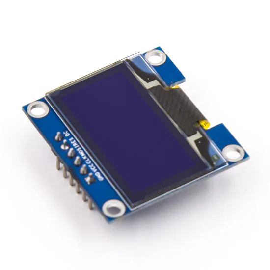
0.96 Inch SPI OLED LCD Module 7-pin (White SSD1306)
Faster refresh SPI OLED perfect for the weather station display station. White on black display ensures maximum readability even in low light conditions.
Weatherproofing and Enclosure Tips
For the outdoor sensor node, proper housing is essential. Here are proven strategies used by Indian makers:
Enclosure selection: Use a junction box rated IP65 or IP67 (widely available at electrical shops for ₹50–150). The DHT22 sensor should be mounted outside the box in a radiation shield (a stack of white plastic discs that prevents direct sunlight from heating the sensor while allowing airflow).
Cable glands: Seal all cable entry points with rubber cable glands to prevent water ingress. Apply silicone sealant around the sensor probe where it passes through the enclosure wall.
Conformal coating: Apply acrylic conformal coating (available in aerosol form) to all PCBs and solder joints. This prevents corrosion from humidity — critical in coastal areas and monsoon seasons.
Antenna orientation: Keep the NRF24L01 module’s antenna oriented vertically (pointing up or down) for best omnidirectional radiation pattern. For the PA+LNA version, route the coaxial cable through a cable gland and mount the antenna on the outside of the enclosure.
Battery housing: Use a sealed 18650 holder inside the IP65 box. In hot Indian summers, lithium cell performance degrades above 45°C — paint the enclosure white to reflect sunlight and reduce internal temperature. For permanent installations, add a small 1W solar panel with a TP4056 LiPo charger module.
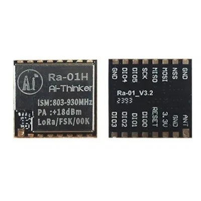
Ai Thinker LoRa Ra-01H Module
Want to upgrade your weather station for farm-scale use? Replace NRF24L01 with LoRa for kilometre-range wireless data transmission — ideal when your outdoor node is far from the display station.
0.96 Inch SPI OLED LCD Module (Blue SSD1306)
Elegant blue OLED display for your indoor weather station hub. The blue-on-black colour scheme gives a premium feel to your weather display unit.
Frequently Asked Questions
How far can the NRF24L01 transmit weather data reliably?
The standard NRF24L01 module achieves 50–100 metres in open space. Through walls, expect 10–30 metres with the basic module. For a distant outdoor sensor (beyond 50m or with multiple walls), use the NRF24L01+PA+LNA module with an external antenna for up to 500 metres range. Alternatively, switch to LoRa for kilometre-scale deployments.
How long will batteries last on the outdoor sensor node?
With the Arduino Nano in power-down sleep mode (about 30 µA) and the NRF24L01 powered off between transmissions, a 3000 mAh 18650 cell can last 3–6 months transmitting every 30 seconds. Optimising further — using a raw ATmega328P instead of a full Nano board, and adding a proper power switch for the NRF24L01 — can push battery life beyond a year.
Can I add more sensor nodes to the same weather network?
Yes. Each additional outdoor node can use a different NRF24L01 pipe address (up to 6 pipes per receiver). The display station reads from all 6 pipes and can show data from up to 6 outdoor nodes simultaneously. For more than 6 nodes, use the RF24Network library which supports tree topology with many more nodes.
Can I log weather data to an SD card or upload it to the internet?
Absolutely. Add an SD card module (SPI) to the display station to log timestamped readings locally. For internet upload, replace the Arduino display station with an ESP32 which can both receive NRF24L01 data (using hardware SPI) and push data to ThingSpeak, Blynk, or a custom server over Wi-Fi.
Why is DHT22 better than DHT11 for a weather station?
The DHT22 has better accuracy (±0.5°C vs ±2°C for DHT11) and a wider range (−40°C to +80°C vs 0–50°C for DHT11). It also has a higher humidity range (0–100% vs 20–80%). For a real weather station, DHT22 is worth the small extra cost. For even better accuracy, pair it with an SHT31 which offers ±0.3°C accuracy and I2C interface.
Get Your Weather Station Components from Zbotic
Zbotic stocks all the components you need for this project — OLED displays, wireless modules, sensors, and development boards — with fast shipping across India. Explore our wireless modules collection and start building your weather station today!


Add comment