
Overcharge Protection Circuit: Prevent Lithium Battery Damage
Lithium batteries are the lifeblood of modern electronics, but they carry a serious risk: overcharge protection circuits for lithium batteries are not optional — they are a safety essential. An overcharged lithium-ion or LiPo cell does not just lose capacity; it can swell, vent toxic gases, catch fire, or in extreme cases, explode. Whether you are building a power bank, an e-bike battery, a custom UPS, or an RC vehicle, understanding how to prevent overcharge damage is fundamental to safe electronics design. This guide explains the mechanisms behind lithium overcharge, the protection methods available, and how to implement them in your projects.
What Happens When a Lithium Cell Overcharges?
A lithium-ion cell has a maximum charge voltage of 4.2V (4.35V for high-voltage NMC cells). A LiPo cell has the same 4.2V limit. These limits exist because of fundamental electrochemistry: above 4.2V, lithium ions begin depositing on the graphite anode in metallic form (lithium plating) rather than intercalating cleanly. Metallic lithium is highly reactive and can pierce the separator — the thin membrane between anode and cathode — causing an internal short circuit.
The Stages of Overcharge Damage
- 4.2V – 4.5V (mild overcharge): Electrolyte oxidation begins. Capacity fade accelerates. Gas generation starts inside the cell, causing slight swelling in LiPo cells. Damage is often not immediately apparent but reduces lifespan significantly.
- 4.5V – 4.8V (moderate overcharge): Significant heat generation. SEI (solid electrolyte interface) breakdown. Visible swelling in LiPo cells. Possibility of electrolyte leakage. The cell should be quarantined and replaced.
- Above 4.8V (severe overcharge): Thermal runaway becomes possible. The cell temperature rises uncontrollably, venting flammable gases. In enclosed spaces or packs, this can cascade to neighboring cells. Fire and explosion risk is real.
In India, many fires in e-bikes, cheap power banks, and improvised UPS systems trace back to missing or failed overcharge protection. The cost of a proper BMS or protection IC is a few hundred rupees — far less than the cost of a house fire or personal injury.
Types of Overcharge Protection Methods
Method 1: Dedicated Charger IC (Most Common)
The simplest approach is to use a charger IC that terminates charging when the cell reaches 4.2V. ICs like the TP4056, LTC4054, MCP73831, and MAX1555 are all constant-current/constant-voltage (CC/CV) chargers that stop charging automatically when voltage reaches the preset 4.2V threshold. The termination is triggered when the charge current drops below 1/10th of the programmed charge current (C/10 termination).
Method 2: Battery Management System (BMS) Board
A BMS board sits between the charger and the battery and monitors individual cell voltages. When any cell exceeds 4.2V (or the preset threshold), the BMS disconnects the charge path using a MOSFET switch. BMS boards also protect against over-discharge, over-current, and short circuits — making them the most comprehensive protection solution.
Method 3: Discrete Circuit with Comparator
For custom or space-constrained designs, a discrete comparator circuit (using an LM393, TL431, or similar IC) can monitor cell voltage and trigger a MOSFET to disconnect the charge path when voltage exceeds the threshold. This approach requires more design effort but offers complete flexibility.
Method 4: Zener Shunt (Emergency Backup Only)
A Zener diode rated at 4.2V placed across the cell acts as a crude voltage clamp. This is not a true protection circuit — the Zener dissipates energy as heat rather than disconnecting the charge path, and can fail short if the power is excessive. Use only as an emergency secondary protection in conjunction with a proper charger IC.

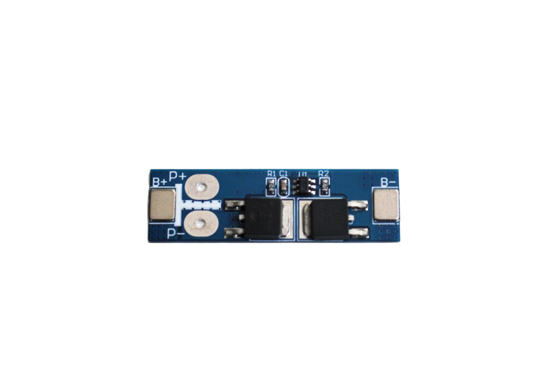
1S 18650 Li-ion Lithium Battery BMS Charger Protection Board for 3.7V Battery
A compact 1S BMS protection board that safeguards your 18650 or LiPo cell from overcharge (4.2V), over-discharge (2.75V), over-current, and short circuits. Essential for any single-cell battery project.
BMS Boards: The Most Practical Solution
For most Indian makers building battery-powered projects, a pre-made BMS board is the fastest and most reliable route to overcharge protection. Here is how to select and wire one correctly.
Key BMS Specifications to Understand
- Cell count: 1S (single cell, 3.7V), 2S (7.4V), 3S (11.1V), etc. Match to your pack configuration.
- Overcharge cutoff voltage: Should be 4.2V +/- 50mV per cell. Some cheaper boards have poor accuracy — test with a multimeter.
- Over-discharge cutoff voltage: Typically 2.75V – 3.0V per cell.
- Continuous current rating: Must exceed your maximum load current. A 5A BMS cannot protect a motor drawing 20A.
- Balance function: Balancing BMS boards also equalize cell voltages in multi-cell packs — important for longevity.
Wiring a 1S BMS Correctly
A 1S BMS has three connection points: B+ and B- connect to the battery’s positive and negative terminals. P+ and P- (or C+ and C-) connect to the charger/load. The BMS internally uses MOSFETs to disconnect either the charge path or discharge path when protection thresholds are triggered. Never bypass the BMS by connecting the load directly to B+ and B- — this defeats the protection entirely.
Common BMS Wiring Mistakes
Many Indian builders make the error of wiring the charger to P+/P- and the load also to P+/P-, which is correct. But some also tie B+ directly to the load as a “backup” — this creates a parallel path that bypasses the MOSFET protection. If a short circuit occurs on the load side, the BMS’s FET disconnects the P- path, but current still flows through the B+ direct connection, potentially causing a fire.
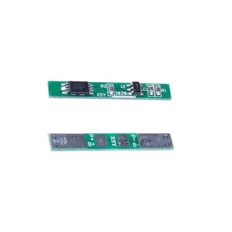
1S 12A 3.6V BMS Battery Protection Board for Li-ion Cell
A high-current 12A 1S BMS board suitable for applications drawing significant current like motors, inverters, and power tools. Provides overcharge, over-discharge, and short-circuit protection for single Li-ion cells.
Building a Discrete Overcharge Protection Circuit
If you want to understand the fundamentals or build protection into a custom PCB, here is how to design a discrete overcharge protection circuit using the DW01A or S-8241 series protection ICs — the same chips used inside most BMS boards.
DW01A-Based Protection Circuit
The DW01A is a single-cell lithium battery protection IC that monitors cell voltage and current. It drives external N-channel MOSFETs to disconnect the charge or discharge path. A typical bill of materials:
- DW01A protection IC (SOT-23-6)
- FS8205A dual N-channel MOSFET (or two separate N-channel MOSFETs like the AO3400)
- 100mO sense resistor (or use PCB trace resistance calibrated to the desired current limit)
- 100nF bypass capacitor on VCC
The DW01A monitors the cell voltage between VCC and VSS. When VCC reaches 4.28V (overcharge threshold), it pulls the CO (charge overprotect) pin low, turning off the charge MOSFET. When VCC drops below 2.4V, it pulls DO (discharge overprotect) low, turning off the discharge MOSFET. Current sensing via the CS pin provides over-current and short-circuit protection.
MOSFET Selection for Back-to-Back Configuration
The protection circuit requires two MOSFETs in a back-to-back configuration (source-to-source connection) rather than a single MOSFET. This arrangement blocks both current directions independently. The FS8205A integrates both FETs in a single package. If using discrete MOSFETs, select N-channel FETs with low Rds(on) (under 20mO for 5A applications) and gate threshold voltage compatible with the DW01A’s output swing (typically 0-3.3V).
1S 3.7V 2A 1MOS BMS Li-ion 18650 Battery Protection Board
A minimal 1S BMS using a single MOSFET design — compact enough for pen-sized gadgets and small wearables. Protects against overcharge, over-discharge, and over-current up to 2A continuous.
Charger ICs with Built-In Protection
Modern charger ICs already implement the constant-current/constant-voltage profile that inherently prevents overcharge — because the CV phase naturally limits the cell at exactly 4.2V. Here is how the most popular ICs handle protection:
TP4056
The TP4056 is the most widely used single-cell charger IC in India. Its 4.2V CV phase is factory-trimmed to 1.5% accuracy. The TP4056 alone handles overcharge but does NOT protect against over-discharge or short circuits on the load side. The widely-sold TP4056 modules with “DW01A + FS8205A” protection (the 4-chip module) combine the charger IC with a separate protection circuit, providing complete protection in a single tiny board.
MCP73831
Microchip’s MCP73831 targets ultra-low current applications (up to 500mA). It includes a PROG pin for charge current setting and an accurate 4.2V (+/-0.75%) charge voltage. Like the TP4056, it covers overcharge but not over-discharge protection — add a separate BMS board for over-discharge protection.
LTC4054 / CN3058
These charger ICs (discussed in our LTC4054 solar charger guide) also regulate accurately at 4.2V. The CN3058 clone has 2% accuracy — marginally acceptable but on the edge of safety margin. The genuine LTC4054 at 1% is preferred for critical applications.
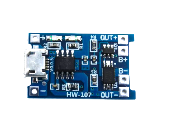
TP4056 1A Li-Ion Battery Charging Board Micro USB with Current Protection
The gold-standard module for single-cell LiPo/Li-ion charging with full protection. Combines TP4056 charger with DW01A+FS8205A over-charge, over-discharge, and short-circuit protection in one tiny module.
Multi-Cell Pack Protection Considerations
Single-cell protection is straightforward. Multi-cell series packs add complexity because each cell must be individually monitored — a pack-level voltage cutoff is insufficient since individual cells can diverge significantly.
Why Pack-Level Cutoff Is Dangerous
In a 3S pack (three cells in series, ~12.6V full charge), a pack-level overvoltage cutoff at 12.6V does not detect that one cell might be at 4.5V while another is only 4.0V. The overcharged cell is silently damaged even though the pack-level voltage appears normal.
Cell-Level Balancing BMS
A proper multi-cell BMS monitors each cell independently and uses balancing resistors or active balancers to equalize cell voltages during charging. When any single cell reaches 4.2V during the balance phase, the BMS either bleeds current through a balancing resistor (passive balancing) or transfers charge to lower-voltage cells (active balancing).
3S BMS Example: 18650 Polymer Charger Module
For Indian makers building 3S packs (commonly used for 12V tools, lights, and UPS), a Type-C to 3S BMS+charger module combines the charging function and protection in one. These modules accept USB-C input and internally regulate to 12.6V CC/CV while monitoring each of the three cells independently.
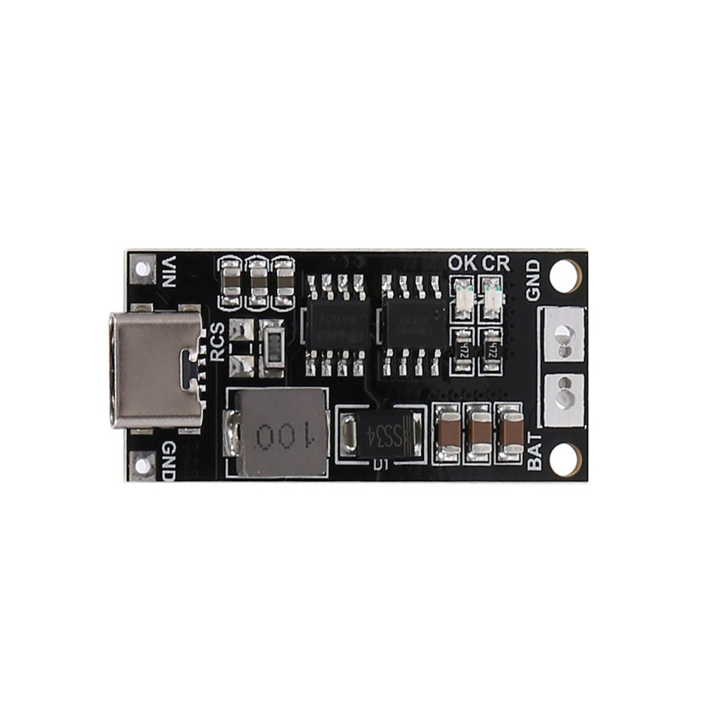
18650 Polymer Lithium Ion Charger Type C to 3S 12.6V 2A Booster Module
All-in-one charging and protection module for 3S 18650 packs. Accepts USB-C input and charges up to 12.6V with 2A current, including individual cell overcharge protection and balancing. Great for DIY 12V power banks and tool batteries.
Testing Your Protection Circuit
Overcharge Cutoff Test
To verify overcharge protection is working, use a bench power supply (not a fixed charger) set to a voltage just above the cutoff threshold (e.g., 4.3V for a 1S protection circuit). Connect through a current-limiting resistor (100 ohms). Monitor the output voltage — the BMS should disconnect the charge path before the battery terminal reaches 4.28V (the typical cutoff). The output should show the supply voltage drop to near 0 when the FET turns off.
Recovery Test
After the overcharge cutoff triggers, the BMS should recover automatically when the supply voltage is removed and the cell voltage drops below the reset threshold (typically 4.0V). Verify recovery by disconnecting the supply briefly, then reconnecting at a lower voltage (4.15V) and confirming the charge path re-enables.
Voltage Accuracy Verification
Using a calibrated multimeter, verify the actual charge termination voltage at the battery terminals. A good BMS should terminate within +/-100mV of the stated 4.2V. If you measure cutoff at 4.4V or higher, the BMS has poor accuracy and should be replaced — it is not providing safe overcharge protection.
Frequently Asked Questions
Can I charge a lithium battery without any protection circuit?
Technically, a quality charger IC like the TP4056 provides overcharge protection inherently through its CC/CV charging algorithm. However, using a bare charger IC without a BMS still leaves the load side unprotected (over-discharge, short circuits). The combination of a charger IC for charging and a BMS for load-side protection is the safest approach.
What happens if the overcharge protection circuit fails?
If the protection MOSFET fails short (stuck on), overcharge protection is lost. This is rare in quality ICs but can happen due to excessive current or heat. Always operate the BMS within its rated current limits and provide thermal management for high-power applications. Some premium BMS boards have dual-FET designs where a second FET provides backup protection.
Is my LiPo safe if it is already slightly swollen?
A slightly swollen LiPo has already undergone some level of electrolyte decomposition. It should be safely discharged to storage voltage (3.7-3.8V), then punctured outdoors in a bucket of sand or saltwater solution to vent the gases before disposal. Never charge a visibly swollen LiPo — the risk of thermal runaway is significantly elevated.
Do I need a separate protection circuit if my charger has CC/CV termination?
A CC/CV charger protects against overcharge during charging. But you also need protection against over-discharge (when the load runs the battery too low) and against short circuits on the output. A BMS covers all three scenarios. For any application where the battery is used in the real world (not just on a lab bench), a BMS is always recommended.
What is the difference between protection and BMS?
A basic protection circuit (like the DW01A+FS8205A combo) only handles overcharge, over-discharge, and short circuits. A full BMS additionally includes cell balancing for multi-cell packs, temperature monitoring, state-of-charge estimation, and communication interfaces (like UART or SMBus for data). For most hobbyist applications, a basic protection circuit is sufficient. For e-bike batteries and power walls, a full BMS with balancing is required.
Protect Your Lithium Batteries Today
Overcharge protection is not a luxury — it is the difference between a reliable battery-powered device and a potential fire hazard. Whether you choose a pre-made BMS board, a TP4056 module with built-in protection, or a custom discrete circuit, Zbotic has all the components you need. Browse our full range of BMS boards and charging modules designed for Indian makers and hobbyists.


Add comment