
A frequency counter Arduino project is one of the most practical and educational builds for intermediate electronics makers. Instead of spending ₹2,000–₹5,000 on a bench frequency counter, you can build one for under ₹500 using an Arduino, a cheap OLED display, and a handful of passive components. Better yet, you’ll understand exactly how frequency measurement works — knowledge that applies to oscillators, signal generators, clock circuits, and radio electronics. This step-by-step guide covers everything from the theory to the complete working code and circuit.
How Frequency Measurement Works
Frequency is defined as the number of cycles (or events) per second, measured in Hertz (Hz). There are two fundamental ways to measure frequency digitally:
Method 1: Counting Events in a Fixed Time Window (Frequency Mode)
Count the number of signal pulses that occur within a precise time window (typically 1 second). Divide the count by the time window duration to get frequency. Simple and accurate for high frequencies where many counts accumulate in the window.
Formula: Frequency = Count / Gate_Time
For example: if you count 1,000 pulses in 1 second, frequency = 1000 Hz = 1 kHz.
Method 2: Measuring Period (Period Mode)
Measure the time between consecutive rising edges of the signal. Frequency = 1 / Period. This method is more accurate for low frequencies where few counts accumulate in the gate time window.
Formula: Frequency = 1 / Period
For a hybrid approach, use frequency mode above ~100 Hz and period mode below ~100 Hz for best accuracy across the entire range.
Arduino Timer Hardware
The ATmega328P in Arduino Uno has three hardware timers (Timer0, Timer1, Timer2). Timer1 is a 16-bit timer and is the most suitable for frequency counting because it can count up to 65,535 pulses before overflow. The TCCR1B register can be configured to count external pulses on digital pin D5 (T1 input) directly in hardware — no interrupts needed for the counting itself.
Components Required
Here is the complete bill of materials for this project. Total estimated cost in India: ₹350–₹600 depending on sourcing.
- Arduino Uno or Nano
- 0.96″ OLED display (SSD1306, I2C, 128×64)
- NE555 timer IC (for test signal generation)
- 2× 1kΩ resistor and 1× 10kΩ resistor
- 1× 100nF ceramic capacitor (0.1µF)
- 1× 10µF electrolytic capacitor
- Breadboard and jumper wires
- USB cable for Arduino power and programming
Optional for input protection: 100Ω series input resistor and 5.1V Zener diode to protect the Arduino counter pin from overvoltage signals.

1.3 Inch I2C 128×64 WHITE OLED Display Module 4pin
The display for this frequency counter project. SH1106 controller, I2C interface, 4 pins — easy to wire and code with the U8g2 library.

0.1/100nF TH Multilayer Ceramic Capacitor (Pack of 50)
Used in the 555 timer oscillator circuit for timing and as decoupling capacitors near ICs. Pack of 50 — enough for many projects.
555 Timer as Test Signal Generator
Before measuring unknown frequencies, it’s essential to test your frequency counter with a known reference signal. The humble NE555 timer in astable mode is perfect for this — it generates a square wave at a frequency determined by external resistors and a capacitor.
Astable 555 Timer Formula
f = 1.44 / ((R1 + 2×R2) × C)
Where R1 = 1kΩ, R2 = 10kΩ, C = 100nF (0.1µF):
f = 1.44 / ((1000 + 20000) × 0.0000001) = 685 Hz
555 Astable Circuit Connections
- Pin 1 (GND) → GND
- Pin 2 (TRIGGER) → Pin 6 (THRESHOLD)
- Pin 3 (OUTPUT) → Frequency counter input (D5)
- Pin 4 (RESET) → VCC
- Pin 5 (CONTROL) → 100nF capacitor to GND
- Pin 6 (THRESHOLD) → Timing capacitor (100nF) to GND
- Pin 7 (DISCHARGE) → Junction of R1 (1kΩ to VCC) and R2 (10kΩ to pin 6)
- Pin 8 (VCC) → 5V
Arduino Frequency Counter: Two Methods
Method A: Hardware Timer Counter (Recommended)
This method uses the ATmega328P’s Timer1 configured as a hardware counter to count pulses on pin D5. The CPU only reads the count register every gate period — no interrupt-driven pulse counting, so it’s highly accurate even at high frequencies.
This approach can measure up to approximately 8 MHz reliably (limited by the Schmitt trigger input threshold speed on the Arduino pin). With a prescaler and signal conditioning, this extends higher.
Method B: pulseIn() / Interrupt Based (Simple but Limited)
Using attachInterrupt() on pin D2/D3 and counting interrupts, you can count up to ~10,000–20,000 Hz before interrupt overhead becomes a limiting factor. Good for learning and low-frequency measurement, not for accurate high-frequency work.
Complete Circuit Diagram Description
OLED Display Connections
- OLED VCC → Arduino 3.3V (or 5V if your OLED is 5V tolerant)
- OLED GND → Arduino GND
- OLED SDA → Arduino A4
- OLED SCL → Arduino A5
Frequency Input Connections
- Signal source → 100Ω input resistor → Arduino D5 (T1 external clock input)
- A 10kΩ pull-down resistor from D5 to GND ensures stable readings when no signal is connected
- Optional: Zener diode (5.1V) from D5 to GND for overvoltage protection
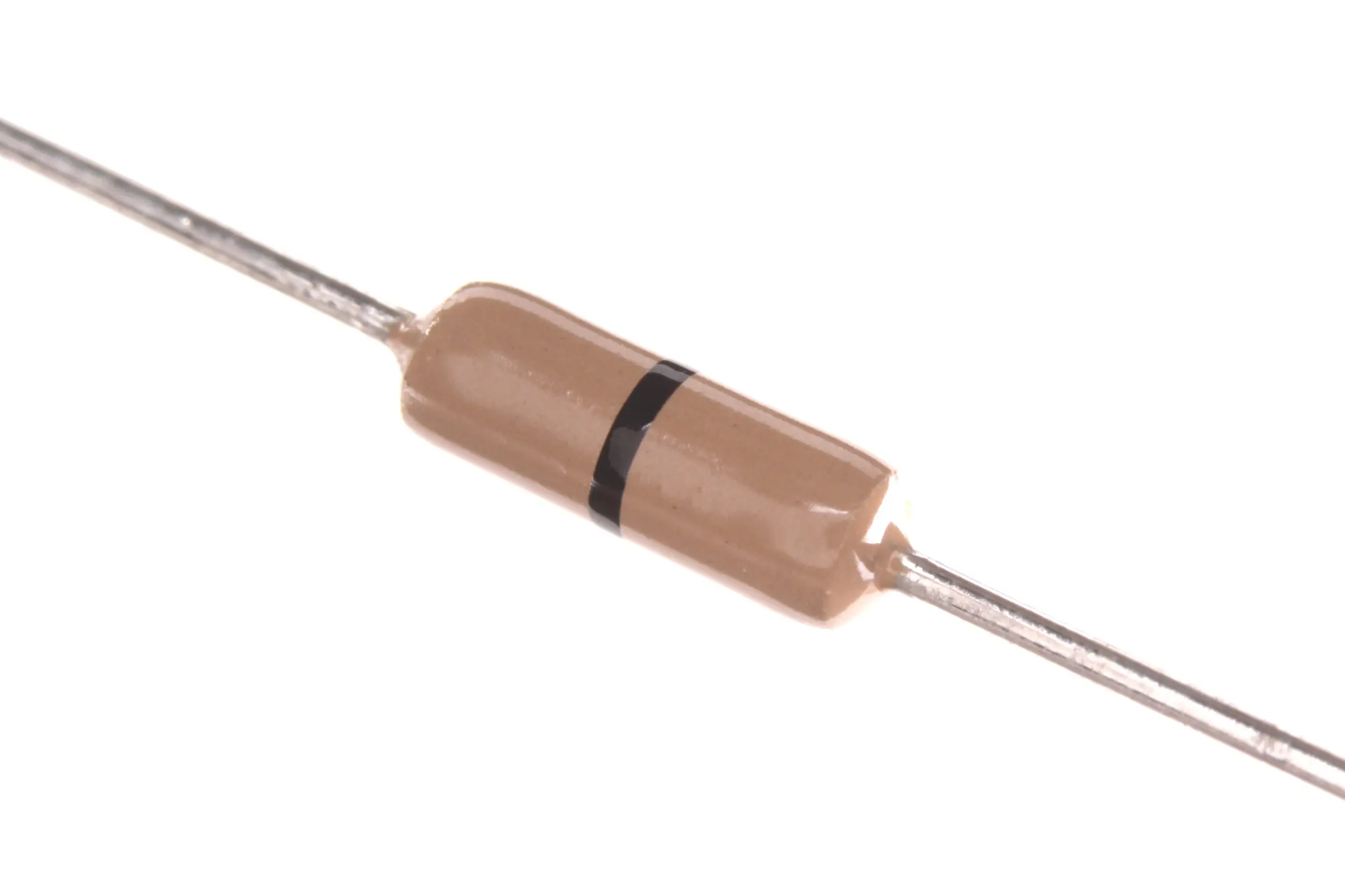
Carbon Film Resistors (Pack of 100)
Needed for the 555 timer oscillator circuit and input protection resistors in this frequency counter project.
Full Arduino Code with OLED Display
This code uses Timer1 in counter mode to count external pulses on D5 with a 1-second gate window, then displays the result on the OLED. Libraries needed: Adafruit_SSD1306 (or U8g2 for the 1.3″ SH1106 display) and Wire.
#include <Wire.h>
#include <Adafruit_GFX.h>
#include <Adafruit_SSD1306.h>

#define SCREEN_WIDTH 128
#define SCREEN_HEIGHT 64
#define OLED_RESET    -1
Adafruit_SSD1306 display(SCREEN_WIDTH, SCREEN_HEIGHT, &Wire, OLED_RESET);

unsigned long frequency = 0;
unsigned long overflowCount = 0;

void setup() {
  Serial.begin(9600);

  // Initialize OLED
  if (!display.begin(SSD1306_SWITCHCAPVCC, 0x3C)) {
    Serial.println("OLED not found!");
    while(1);
  }
  display.clearDisplay();
  display.setTextColor(SSD1306_WHITE);
  display.setCursor(10, 20);
  display.setTextSize(1);
  display.println("Frequency Counter");
  display.println("  zbotic.in");
  display.display();
  delay(2000);

  // Configure Timer1 as external counter on D5
  // TCCR1A: normal mode
  // TCCR1B: clock from T1 pin, rising edge
  TCCR1A = 0;
  TCCR1B = (1 << CS12) | (1 << CS11) | (1 << CS10); // External, rising edge
  TCNT1 = 0;   // Reset counter

  // Timer1 overflow interrupt
  TIMSK1 = (1 << TOIE1);
  sei(); // Enable global interrupts
}

// Timer1 overflow ISR — counts each 65536 pulses
ISR(TIMER1_OVF_vect) {
  overflowCount++;
}

void loop() {
  overflowCount = 0;
  TCNT1 = 0; // Reset counter

  delay(1000); // 1-second gate window

  // Stop counting briefly to read
  uint8_t savedTCCR1B = TCCR1B;
  TCCR1B = 0; // Stop timer

  unsigned long counts = TCNT1 + (overflowCount * 65536UL);
  frequency = counts; // counts per second = Hz

  TCCR1B = savedTCCR1B; // Resume counting

  // Display on OLED
  display.clearDisplay();
  display.setTextSize(1);
  display.setCursor(0, 0);
  display.println("-- Frequency Counter --");

  display.setCursor(0, 20);
  display.setTextSize(2);

  if (frequency >= 1000000) {
    float mhz = frequency / 1000000.0;
    display.print(mhz, 3);
    display.println(" MHz");
  } else if (frequency >= 1000) {
    float khz = frequency / 1000.0;
    display.print(khz, 2);
    display.println(" kHz");
  } else {
    display.print(frequency);
    display.println(" Hz");
  }

  display.setTextSize(1);
  display.setCursor(0, 55);
  display.print("Gate: 1s | Counts: ");
  display.println(counts);
  display.display();

  // Also print to Serial
  Serial.print("Frequency: "); Serial.print(frequency); Serial.println(" Hz");
}
Code Explanation
TCCR1B = (1<<CS12)|(1<<CS11)|(1<<CS10): Configures Timer1 to count external pulses on pin D5, incrementing on each rising edge- The ISR counts Timer1 overflows (every 65,536 pulses) to extend measurement range
- After exactly 1 second, read TCNT1 + overflow × 65536 = total pulse count = frequency in Hz
- Auto-scales display between Hz, kHz, and MHz
Testing and Calibration
Step-by-Step Test Procedure
- Connect the 555 timer astable circuit as described above
- Upload the code and open Serial Monitor at 9600 baud
- Connect the 555 output (pin 3) to Arduino D5
- The display should show approximately 685 Hz (the calculated 555 frequency)
- Verify against the formula: adjust R2 value and verify the display changes accordingly
Accuracy Notes
The accuracy of this frequency counter is limited by the Arduino’s crystal oscillator accuracy — typically ±0.5% for Arduino Uno. For a reference frequency of 1,000 Hz, the reading may vary by ±5 Hz. For higher accuracy, use an Arduino with an external temperature-compensated crystal oscillator (TCXO) reference, or calibrate against a known accurate source.

10CM Male To Female Breadboard Jumper Wires 2.54MM – 40Pcs
Connect your OLED display module and 555 timer circuit to the Arduino with these colour-coded jumper wires.
Project Extensions and Upgrades
1. Auto-ranging Gate Time
Use 100ms gate for very high frequencies (>100kHz) and 10-second gate for very low frequencies (<10Hz). Measure once at 100ms, then decide the optimal gate time for the next measurement for faster updates on the display.
2. Min/Max Memory
Store the minimum and maximum measured frequencies in variables and display them alongside the current reading. Useful for monitoring oscillator stability over time.
3. Temperature-Compensated Reference
The Arduino’s ceramic resonator drifts with temperature. Add a DS3231 RTC module (which has a TCXO inside) and use its 32 kHz output as a calibration reference to correct the counter’s readings.
4. Input Amplifier for Small Signals
The Arduino’s digital input threshold is ~1.5V. For measuring frequencies from small signals (e.g. from a coil or antenna), add a simple transistor amplifier stage or a comparator (LM393) to clean and amplify the input before it reaches D5.
5. Measure RPM
Mount a hall-effect sensor or IR phototransistor to count rotations per second, multiply by 60 to display RPM. Perfect for monitoring motor speed in robotics projects.
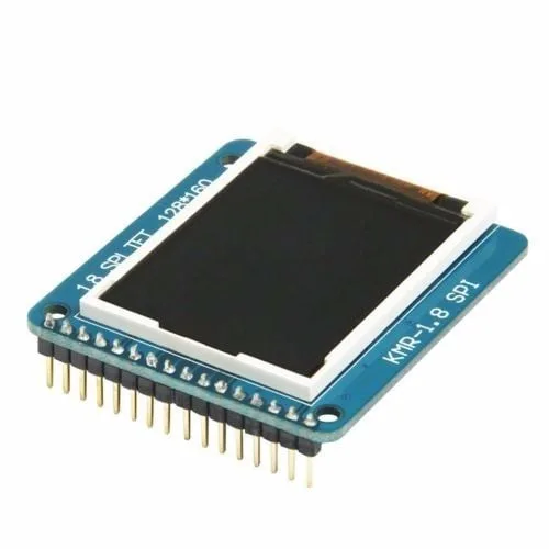
1.8 Inch SPI 128×160 TFT LCD Display Module for Arduino
Upgrade your frequency counter with this colour TFT display for a more impressive readout. Shows frequency trends in a graph.
Frequently Asked Questions
Q1: What is the maximum frequency this Arduino counter can measure?
Using the hardware Timer1 counter mode, the theoretical maximum is limited by the ATmega328P’s input specification for the T1 pin — approximately 8–10 MHz for a clean square wave input. Practical reliable range is 1 Hz to ~1 MHz. Beyond this, you need a prescaler IC (like a 74HC4040 ripple counter) that divides the input frequency before feeding it to the Arduino, then multiply the result by the division factor in software.
Q2: Can I use an Arduino Nano instead of Uno for this project?
Yes, the Arduino Nano uses the same ATmega328P microcontroller. The T1 external counter input is on pin D5 on both Uno and Nano. The only difference is physical size — Nano is smaller, which is useful if you want to build a handheld frequency counter. The code works identically on both boards.
Q3: Why does my frequency reading fluctuate even with a stable 555 signal?
This is normal and expected due to the ±1 count quantization error in frequency measurement. If your gate time is 1 second and the signal is 685 Hz, the reading will alternate between 685 and 686 Hz (or nearby values). This is the fundamental limit of the counting method. To reduce fluctuation, average multiple readings in software, or use a longer gate time for better resolution.
Q4: How can I measure AC mains frequency (50 Hz) with this counter?
Use a small transformer to step down 230V AC to ~6V AC, then a diode bridge to get pulsing DC, and a comparator (LM393) or transistor to convert to clean 5V logic-level pulses. Feed this 100 Hz signal (two pulses per cycle) to D5, then divide the count by 2. Important: never connect mains voltage directly to an Arduino — always use proper isolation.
Q5: Can this project be used to measure the clock frequency of other ICs?
Yes! This is one of the most practical applications. You can probe the clock output pin of a 555, a crystal oscillator can, an NE567 tone decoder, or any other oscillator circuit to verify its actual operating frequency. This is an invaluable debugging tool when your circuit timing seems off.
Build This Project with Parts from Zbotic
All the components for this frequency counter — OLED displays, capacitors, resistors, and Arduino accessories — are available at Zbotic with fast delivery across India.


Add comment