
Manual window blinds are a daily annoyance — you walk across the room, twist the rod, adjust for glare, walk back, realise the angle is still wrong, and repeat. An automatic blinds controller with a stepper motor solves this permanently. With a weekend of work and components costing under ₹1500, you can have your blinds respond to a schedule, a button press, voice commands via Alexa/Google Home, or even a light sensor.
This complete project guide covers everything: the hardware architecture, stepper motor selection, wiring, Arduino code, ESP32 Wi-Fi control, mechanical installation, and extending with smart home integration.
How Motorised Blinds Work
Most horizontal venetian blinds and roller blinds use a simple tilt rod or lift cord mechanism:
- Tilt rod (louvre angle control): Rotating the rod changes the angle of the horizontal slats. One full rotation typically tilts from fully open to fully closed. This is the easiest mechanism to motorise.
- Lift cord (raise/lower): Pulling the cord raises or lowers the entire blind. Motorising this needs a cord winding spool and more torque.
- Roller blinds: The blind rolls up/down on a spring-tensioned tube. You replace or supplement the spring mechanism with a motor on the roller tube end.
For this project, we’ll focus on tilt rod control — it’s the most straightforward to motorise, requires the least torque, and gives you the most useful daily control (light level adjustment without fully opening/closing).
Why Use a Stepper Motor?
Stepper motors are the ideal choice for this application for three key reasons:
- Precise position control: A stepper moves in fixed angular steps (1.8° per step for a standard motor = 200 steps per revolution). You always know exactly what angle your blinds are at — no potentiometer or encoder needed.
- Holding torque at rest: Steppers maintain position by keeping current in the windings. Your blinds won’t drift to a different angle on their own.
- Simple control: A basic A4988 or ULN2003 driver makes stepper control trivial from any microcontroller.
Which Stepper for Blinds?
28BYJ-48 (5V, with ULN2003 driver): This is the ideal choice for tilt rod control. It’s cheap (~₹60), has a built-in 1:64 gear reduction giving very high torque (enough to twist any standard blind tilt rod), runs on 5V, and the ULN2003 driver board is included in most kits. Its low speed is actually an advantage here — smooth, controlled rotation.
NEMA17 (with A4988 driver): Overkill for tilt control, but necessary if you’re lifting the entire blind via cord. More torque (5.6 kg-cm vs ~34 g-cm), faster, but requires 12V supply and more complex wiring.
Components List & Cost
| Component | Quantity | Approx Cost (₹) |
|---|---|---|
| 28BYJ-48 Stepper + ULN2003 Driver | 1 | ₹70 – ₹90 |
| ESP32 DevKit (for Wi-Fi) or Arduino Uno | 1 | ₹350 – ₹500 |
| 5V 2A Power Supply / USB adapter | 1 | ₹120 – ₹200 |
| Push button (for manual control) | 2 | ₹20 |
| LDR (light sensor, optional) | 1 | ₹10 |
| 3D-printed or custom coupling bracket | 1 | ₹50 – ₹100 (filament) |
| Jumper wires, breadboard, project box | various | ₹100 |
| Total (approx) | — | ₹720 – ₹1020 |
Circuit Wiring Diagram
The wiring for the 28BYJ-48 + ULN2003 with an ESP32 is minimal:
ULN2003 Driver to ESP32
- IN1 → GPIO 27
- IN2 → GPIO 26
- IN3 → GPIO 25
- IN4 → GPIO 33
- GND → GND
- 5V-12V power terminal → 5V supply (separate from ESP32’s 3.3V)
The stepper motor plugs directly into the ULN2003 board via its 5-pin connector. No additional components needed.
Manual Control Buttons
- Button 1 (Open): One pin to GPIO 14, other pin to GND. Enable internal pullup in code.
- Button 2 (Close): One pin to GPIO 12, other pin to GND.
Optional LDR Auto-Tilt
- LDR + 10kΩ resistor as voltage divider → GPIO 34 (ADC input on ESP32)
- Connect LDR between 3.3V and the GPIO pin, 10kΩ between GPIO pin and GND
Arduino / ESP32 Code
Basic Stepper Control with Tilt Position Tracking
#include <Stepper.h>

// 28BYJ-48: 2048 steps per revolution (after gear reduction)
const int STEPS_PER_REV = 2048;
const int STEPS_PER_TILT = 512; // ~90 degrees = one-quarter revolution

Stepper blindsStepper(STEPS_PER_REV, 27, 25, 26, 33); // IN1, IN3, IN2, IN4 order!

int currentPosition = 0;  // 0 = open, STEPS_PER_TILT = closed

void setup() {
  blindsStepper.setSpeed(10); // RPM — 10 RPM is smooth and quiet
  Serial.begin(115200);
  Serial.println("Blinds controller ready");
}

void openBlinds() {
  if (currentPosition > 0) {
    blindsStepper.step(-currentPosition); // Step back to 0
    currentPosition = 0;
    Serial.println("Blinds: OPEN");
  }
}

void closeBlinds() {
  int stepsNeeded = STEPS_PER_TILT - currentPosition;
  if (stepsNeeded > 0) {
    blindsStepper.step(stepsNeeded);
    currentPosition = STEPS_PER_TILT;
    Serial.println("Blinds: CLOSED");
  }
}

void setTilt(int percent) { // 0 = open, 100 = fully closed
  int targetSteps = map(percent, 0, 100, 0, STEPS_PER_TILT);
  int delta = targetSteps - currentPosition;
  blindsStepper.step(delta);
  currentPosition = targetSteps;
}

void loop() {
  // Add button or serial command handling here
  if (Serial.available()) {
    char cmd = Serial.read();
    if (cmd == 'o') openBlinds();
    if (cmd == 'c') closeBlinds();
    if (cmd == 'h') setTilt(50); // Half-open
  }
}
Note on step order: The 28BYJ-48 uses a specific coil sequence. The Arduino Stepper library uses IN1,IN3,IN2,IN4 order (not IN1,IN2,IN3,IN4) for this motor. If the motor hums but doesn’t move, recheck the pin order in the Stepper constructor.
ESP32 Wi-Fi HTTP Control Server
#include <WiFi.h>
#include <WebServer.h>
#include <Stepper.h>

const char* ssid = "YOUR_WIFI_SSID";
const char* password = "YOUR_WIFI_PASSWORD";

WebServer server(80);
Stepper blindsStepper(2048, 27, 25, 26, 33);
int currentPosition = 0;
const int STEPS_CLOSED = 512;

void handleOpen() {
  blindsStepper.step(-currentPosition);
  currentPosition = 0;
  server.send(200, "text/plain", "Blinds opened");
}

void handleClose() {
  blindsStepper.step(STEPS_CLOSED - currentPosition);
  currentPosition = STEPS_CLOSED;
  server.send(200, "text/plain", "Blinds closed");
}

void handleTilt() {
  if (server.hasArg("percent")) {
    int pct = server.arg("percent").toInt();
    int target = map(pct, 0, 100, 0, STEPS_CLOSED);
    blindsStepper.step(target - currentPosition);
    currentPosition = target;
    server.send(200, "text/plain", "Tilt set to " + String(pct) + "%");
  } else {
    server.send(400, "text/plain", "Missing percent parameter");
  }
}

void setup() {
  blindsStepper.setSpeed(10);
  WiFi.begin(ssid, password);
  while (WiFi.status() != WL_CONNECTED) delay(500);
  Serial.begin(115200);
  Serial.println("IP: " + WiFi.localIP().toString());
  server.on("/open", handleOpen);
  server.on("/close", handleClose);
  server.on("/tilt", handleTilt);
  server.begin();
}

void loop() {
  server.handleClient();
}
With this code, you can control your blinds by visiting http://[ESP32-IP]/open, /close, or /tilt?percent=50 from any device on your home network.
Mechanical Installation
The software is easy — the mechanical coupling is where most builders spend the most time. Here are the key approaches:
Option 1: Shaft Coupler (Cleanest Method)
The 28BYJ-48 has a 5mm flatted output shaft. Standard blind tilt rods are typically 5mm or 6mm square/hex sections. Options:
- 3D-print a coupler that accepts the motor shaft on one end and the tilt rod on the other
- Use a flexible shaft coupler to accommodate slight misalignment
- Use a rubber tube or heat-shrink sleeve as a simple friction coupling for light-duty use
Option 2: External Wand Drive
Instead of coupling directly to the tilt rod, attach a small arm to the motor shaft and link it to the existing manual wand with a rigid wire. This avoids disassembling the blind bracket entirely.
Option 3: Cord Wheel (for Roller Blinds)
For roller blinds, replace the spring mechanism with a motorised drum that winds/unwinds the cord. Use a NEMA17 stepper with an A4988 driver for the torque needed. Mount in a 3D-printed bracket that replaces the blind’s end cap.
Mounting the Controller Box
- Mount the motor and controller in a small 3D-printed or bought enclosure on the blind’s headrail
- Use double-sided tape or adhesive velcro strips for reversible mounting
- Run power cable along the wall/skirting to the nearest socket
- For battery-powered operation: 4× AA NiMH cells (4.8V) power the 28BYJ-48 for weeks of normal use
Smart Home Integration (Alexa, Google)
Once the ESP32 is on your Wi-Fi network, you can integrate it with smart home platforms in several ways:
ESPHome (Easiest for Home Assistant)
Flash ESPHome firmware to your ESP32. Define the stepper motor as a “cover” entity. Home Assistant automatically discovers it and exposes it to Google Home and Amazon Alexa via the Home Assistant cloud or Nabu Casa.
Sinric Pro (Alexa/Google without Home Assistant)
Sinric Pro is a free cloud service that bridges ESP32 devices directly to Alexa and Google Home. Add the Sinric Pro library to your ESP32 sketch, register a “blind” device in the Sinric Pro dashboard, and say “Alexa, open the bedroom blinds.”
Blynk (Mobile App Control)
The Blynk IoT platform lets you build a custom mobile dashboard with sliders and buttons. The Blynk library for ESP32 connects to their cloud server. You can add a slider for tilt percentage and buttons for open/close — works from anywhere over the internet, not just your home Wi-Fi.
MQTT (Maximum Flexibility)
For advanced users: publish commands to an MQTT broker (like Mosquitto on a Raspberry Pi) and subscribe to topics in your ESP32 code. Integrates with Node-RED, Home Assistant, or any automation system.
Troubleshooting Common Issues
Motor Makes Noise But Doesn’t Move
This is almost always a pin order issue with the 28BYJ-48. Try swapping IN2 and IN3 pins in your code, or use the AccelStepper library which has a specific mode for the 28BYJ-48 with half-stepping (mode 8).
Motor Moves Wrong Direction
Either reverse the direction parameter in your step() call (use negative values) or physically swap the motor connector 180°.
Motor Overheats After 5 Minutes
The 28BYJ-48 holds current in the coils whenever the driver is enabled, even when not moving. After completing a move, cut the enable pins or set all driver outputs LOW to release the coils. The motor gearbox provides enough friction to hold the tilt rod position without current.
// After each move, release coils to prevent overheating
void releaseStepper() {
  digitalWrite(27, LOW);
  digitalWrite(26, LOW);
  digitalWrite(25, LOW);
  digitalWrite(33, LOW);
}
Position Drifts Over Time
If your blind angle slowly drifts from the commanded position, you’re likely losing steps due to insufficient torque or too-high speed. Reduce speed (lower RPM setting), check power supply can deliver sufficient current, and add limit switch calibration (re-home to the fully-open position once per day).
Components Available at Zbotic
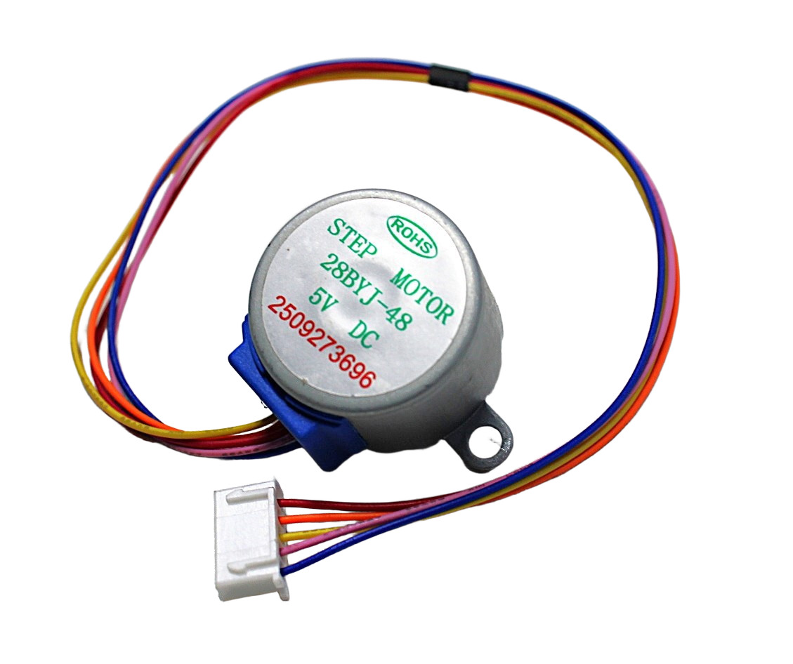
28BYJ-48 5V Stepper Motor
The perfect stepper for blind tilt control — built-in 1:64 gearbox, high torque, runs on 5V, compact and quiet. The go-to choice for this project.

NEMA17 5.6 kg-cm Stepper Motor with Detachable Cable
For heavy roller blinds or cord-lift blinds needing serious torque. 5.6 kg-cm holding torque handles even large blackout roller blinds.

A4988 Stepper Motor Driver Controller Board
Pair with NEMA17 for precise microstepping control (up to 1/16 step). Adjustable current limiting protects your motor. Red board for easy identification.
Frequently Asked Questions
Q1: How do I know if my blinds have a tilt rod or lift cord?
Horizontal venetian blinds (the type with horizontal slats) use a tilt rod — you can see it as a round or square rod running the length of the blind at the top, with a wand hanging down from one end. Roller blinds (single fabric roll) use a cord or spring lift mechanism. Vertical blinds use a different track system. This project covers horizontal venetian tilt rod motorisation primarily.
Q2: Will this project work with smart assistants like Alexa?
Yes, with the Sinric Pro or ESPHome integration described in the Smart Home section. You’ll need an ESP32 (not a basic Arduino Uno, which lacks Wi-Fi). With Sinric Pro, setup takes about 20 minutes and works with both Alexa and Google Home for free.
Q3: How do I handle multiple blinds in different rooms?
Build one controller per blind. Each ESP32 gets a unique IP address and Sinric Pro device name. In Alexa or Google Home, you can group them (e.g., “bedroom blinds,” “living room blinds”) and control them together with a single command.
Q4: My ESP32 reboots when the stepper motor starts — why?
The 28BYJ-48 draws up to 240mA. If you’re powering the motor from the ESP32’s 3.3V or 5V pin, this can cause brownout resets. Always power the ULN2003 board from a separate 5V supply (phone charger, USB supply), sharing only GND with the ESP32.
Q5: Can I save the blind position to survive power cuts?
Yes — use ESP32’s built-in Preferences library (EEPROM emulation in flash) to save the current step position. On boot, read the saved position and use it as the starting point. For reliability, also add a simple limit switch at the fully-open position to re-home on startup.
Conclusion
Building an automatic blinds controller with a stepper motor is one of the most satisfying home automation projects you can complete in a weekend. The 28BYJ-48 stepper provides more than enough torque for tilt rod control, the ESP32 adds Wi-Fi for remote and smart home control, and the total cost stays well under ₹1000 for basic functionality.
The key insight that makes this project easy: stepper motors don’t need position sensors for this application — the gear reduction provides enough holding torque to maintain the tilt angle, and you track position in software by counting steps. Start with serial control, add push buttons, then extend to Wi-Fi — each step is independently functional.
Build Your Smart Home Automation Project
Get all the stepper motors, drivers, and microcontrollers you need for your blinds controller — fast delivery across India from Zbotic.


Add comment