
Microstepping is one of the most misunderstood concepts in stepper motor control. Many makers set their drivers to 1/16 microstepping believing it gives 16× more precision and quieter operation — but the full picture is more nuanced. Microstepping increases theoretical resolution, reduces vibration, and smooths motion, but it also reduces available torque at each microstep. This guide explains every microstepping mode, the engineering behind it, and the right settings for your project.
Full Step Basics: How a Stepper Motor Moves
A bipolar stepper motor has two coil pairs (A and B). In full-step mode, both coils are driven at maximum current, alternating in a four-step sequence: A+B+, A-B+, A-B-, A+B-. Each state energises a rotor tooth into a specific position. A standard 1.8° stepper motor has 50 rotor teeth, resulting in 200 full steps per revolution (360° / 1.8° = 200).
The problem with full stepping is that the rotor snaps abruptly between positions. This creates audible clicking, mechanical resonance at certain speeds, and visible stepping in linear motion (a phenomenon called “staircase artefact” in 3D printing).
Half-Step Mode
Before microstepping, half-step mode was introduced. Instead of switching both coils simultaneously, the driver alternates between energising one coil (maximum force in one direction) and both coils simultaneously (force at 45° between two poles). This doubles the step count to 400 per revolution (0.9° per step) and reduces vibration slightly, but the torque varies significantly between the one-coil and two-coil states.
What Is Microstepping?
Microstepping uses sinusoidal current waveforms in the two coils to position the rotor between the discrete full-step positions. Instead of abruptly switching from one current state to the next, the driver gradually increases current in one coil while decreasing it in the other, tracing a smooth sine/cosine wave.
The mathematics: at 1/16 microstepping, the driver steps through 16 current levels between each full-step position. Coil A current follows a cosine curve, Coil B follows a sine curve. The rotor’s attraction to the resulting magnetic field vector causes it to move smoothly through 16 intermediate positions between each natural full-step detent.
The result is smoother motion, lower vibration, and (in theory) finer positioning — but with an important caveat about torque that most guides skip.
Microstepping Modes: 1/2, 1/4, 1/8, 1/16, 1/32, 1/256
| Mode | Steps/Rev (1.8° motor) | Step Angle | Relative Torque | Noise Reduction |
|---|---|---|---|---|
| Full (1/1) | 200 | 1.8° | 100% | Baseline |
| 1/2 | 400 | 0.9° | ~71% | Low |
| 1/4 | 800 | 0.45° | ~38% | Moderate |
| 1/8 | 1,600 | 0.225° | ~19% | Good |
| 1/16 | 3,200 | 0.1125° | ~10% | Excellent |
| 1/32 | 6,400 | 0.05625° | ~5% | Excellent |
| 1/256 | 51,200 | 0.007° | <1% | Near-silent |
Important note on torque values: The relative torque figures above assume the single microstep holding torque at that position. The actual torque available to overcome friction or mechanical load at each microstep decreases proportionally. This is why microstepping is not just a free upgrade — you are trading torque for smoothness.
Torque vs Resolution Trade-off
The torque at a given microstep position is proportional to sin(π/N), where N is the number of microsteps. At 1/16, the torque per microstep is sin(π/16) ≈ 0.195, or about 19.5% of full-step torque. At 1/256, it drops to about 1.2%.
What This Means in Practice
- At 1/16 microstepping, your motor can easily slip a few microsteps under load — but because the error is always less than one full step, the motor generally self-corrects as it passes through the full-step detent positions.
- In 3D printing, this means the actual positioning accuracy does not scale linearly with microstepping. The motor tends to snap to full-step positions under load, regardless of the microstep setting.
- For high-load CNC machining (aluminium, hardwood), full or 1/2 step mode maximises torque. Use 1/8 for a practical balance of torque and vibration reduction.
The Practical Precision Reality
In a well-calibrated 3D printer with a GT2 belt and 20T pulley, the linear distance per full step is: (2 mm belt pitch × 20 teeth) / 200 steps = 0.2 mm per full step. At 1/16 microstepping, this is theoretically 0.0125 mm (12.5 microns) per microstep. However, belt elasticity alone introduces 50–100 micron positional uncertainty. Microstepping beyond 1/8 or 1/16 provides no measurable improvement in actual print quality on belt-driven systems.
Noise & Vibration: Why Microstepping Helps
Even if high microstepping doesn’t improve dimensional accuracy, it dramatically reduces noise and vibration — which matter for several reasons:
- Resonance: Stepper motors have natural resonance frequencies (typically 50–150 Hz in full step). At resonance, the motor vibrates violently and can miss steps. Microstepping shifts and dampens resonance modes.
- Ringing artefacts: In 3D printing, motor vibration creates surface ringing (“ghosting”) visible as wavy patterns next to sharp corners. Higher microstepping reduces but doesn’t eliminate ringing — input shaping (Klipper) is more effective.
- Bearing wear: Vibration accelerates bearing fatigue. A machine running at 1/16 microstepping will have quieter bearings and longer service life than the same machine at full step.
- Structural resonance: Frame vibration from full-step operation can loosen M3 screws, degrade print quality, and annoy people working nearby.
Driver Configuration: A4988 MS Pins Explained
The A4988 uses three logic pins — MS1, MS2, MS3 — to set microstepping mode. The combinations are:
| MS1 | MS2 | MS3 | Microstepping Mode |
|---|---|---|---|
| LOW | LOW | LOW | Full Step |
| HIGH | LOW | LOW | 1/2 Step |
| LOW | HIGH | LOW | 1/4 Step |
| HIGH | HIGH | LOW | 1/8 Step |
| HIGH | HIGH | HIGH | 1/16 Step |
On RAMPS 1.4 and most Arduino-based 3D printer boards, the MS pins are pulled HIGH via 100K resistors, defaulting to 1/16. To change modes, you typically place or remove jumpers under the driver socket. On RAMPS: 3 jumpers = 1/16 (default), 2 jumpers = 1/8, 1 jumper = 1/4, no jumpers = full step.
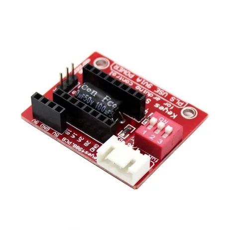
A4988 Stepper Motor Driver Controller Board – RED
The A4988 supports full, 1/2, 1/4, 1/8, and 1/16 microstepping via MS1/MS2/MS3 pins. It is the standard driver for entry-level 3D printers and CNC machines in India — compatible with RAMPS 1.4, MKS Gen L, and Arduino Mega-based boards.
Calculating Steps-per-mm for Your Machine
Once you set a microstepping mode, you must update your firmware’s steps-per-mm values. The formula:
Steps/mm = (Motor steps/rev × Microstepping factor) / (Lead or pitch)
Examples
- 3D printer X/Y (GT2 belt, 20T pulley, 1/16 microstepping):
Steps/mm = (200 × 16) / (2 × 20) = 3200 / 40 = 80 steps/mm - 3D printer Z (T8 lead screw with 2mm pitch, 4-start = 8mm/rev, 1/16):
Steps/mm = (200 × 16) / 8 = 400 steps/mm - CNC router X/Y (T8 lead screw, 8mm/rev, 1/8 microstepping):
Steps/mm = (200 × 8) / 8 = 200 steps/mm - Extruder (direct drive, 7.5mm effective diameter, 1/16):
Steps/mm = (200 × 16) / (π × 7.5) ≈ 135.8 steps/mm (calibrate empirically)
Best Microstepping Settings for 3D Printers & CNC
FDM 3D Printers
- X/Y axes: 1/16 (A4988) or 1/16 to 1/256 (TMC2209 with interpolation) — use highest available for quietness
- Z-axis: 1/16 is more than sufficient; lead screws are slow and torque matters more than resolution
- Extruder: 1/16 standard; if using pressure advance on Klipper, higher microstepping can improve retraction precision
CNC Router (Wood/Plastic)
- All axes: 1/8 to 1/16 — good balance of torque and smoothness for routing operations
CNC Router (Aluminium Milling)
- All axes: 1/4 to 1/8 — prioritise torque and step reliability over resolution. Mechanical accuracy from the lead screw far exceeds stepper resolution at any microstepping level.
Laser Engravers
- All axes: 1/16 to 1/32 — laser engravers benefit from the smoothest possible motion to avoid surface texture artefacts on smooth engraving
StealthChop vs SpreadCycle (TMC Drivers)
TMC2208, TMC2209, and TMC5160 drivers from Trinamic (now Analog Devices) use two proprietary current control modes:
StealthChop
StealthChop uses voltage-mode (not current-mode) control at low speeds. The result is near-silent operation — the motor’s switching frequency is inaudible. At high speeds, StealthChop can lose torque or stall. Most 3D printer firmware (Marlin, Klipper) defaults to StealthChop below a threshold speed and automatically switches to SpreadCycle above it.
SpreadCycle
SpreadCycle is a current-mode control that maintains precise current regulation across all speeds. It is noisier than StealthChop but provides consistent torque at high print speeds. For print speeds above 150 mm/s, SpreadCycle (or hybrid mode) is more reliable.
Interpolation to 1/256
TMC drivers use hardware interpolation: regardless of the microstepping set by the MS pins, the internal stepper interpolates to 1/256 microsteps for smooth current waveform generation. This means a TMC2209 set to 1/16 via MS pins still drives the motor with 256-level sine waves internally — combining the simplicity of 1/16 step counting with the smoothness of 1/256.

42HS48-1204A-20F NEMA17 5.6 kg-cm Stepper Motor – D-Type Shaft
A 200-step/rev (1.8°) NEMA 17 motor that works with all microstepping modes from full step to 1/256 on TMC drivers. The D-type shaft ensures secure pulley or coupling attachment on CNC and 3D printer axes.
Frequently Asked Questions
Does higher microstepping improve 3D print quality?
Not significantly beyond 1/16 on belt-driven printers. Belt elasticity and real-world load cause the motor to snap to full-step positions under force, regardless of microstepping setting. The main benefit of high microstepping is reduced noise and vibration, which indirectly reduces surface ringing artefacts.
What is the default microstepping on an Ender 3?
The stock Ender 3 uses A4988 drivers set to 1/16 microstepping via three jumpers on the RAMPS-equivalent board. The firmware is configured for 80 steps/mm on X and Y axes (GT2 belt, 20T pulley, 200 steps/rev, 1/16) and 400 steps/mm on Z (T8 lead screw, 8 mm/rev, 1/16).
Can I change microstepping without updating firmware?
No. If you change the physical microstepping setting (MS pins or jumpers), you must update the steps-per-mm in your firmware (or EEPROM via M92 command) to match. Mismatched settings will cause incorrect movement distances — your prints or CNC parts will be scaled incorrectly.
What microstepping should I use for a CNC router cutting aluminium?
Use 1/4 or 1/8 microstepping for aluminium CNC work. These modes provide significantly more torque per step than 1/16, reducing the risk of stall during heavy cutting passes. The dimensional precision of a lead screw system is set by the screw pitch, not by microstepping resolution.
Does microstepping make stepper motors quieter?
Yes. Higher microstepping modes use smoother sinusoidal current waveforms that reduce the acoustic noise and vibration from the motor. 1/16 microstepping on an A4988 is noticeably quieter than full step. TMC2209 drivers with StealthChop at 1/16 (with internal 1/256 interpolation) are dramatically quieter — often near-silent at low speeds.
Get Your Stepper Motors & Drivers
Zbotic.in stocks NEMA 17 stepper motors, A4988 driver boards, and a wide range of motion control components for 3D printers and CNC machines. All ships across India with fast delivery.


Add comment