
The TB6600 stepper motor driver is one of the most popular high-current stepper drivers available for hobbyists, makers, and engineers in India. Whether you are building a CNC router, a 3D printer, a robotic arm, or any precision motion control system, the TB6600 offers a reliable combination of high current capacity, adjustable microstepping, and simple wiring that makes it an excellent upgrade over lower-power drivers like the A4988 or DRV8825.
This comprehensive guide covers everything you need to know about the TB6600: its specifications, DIP switch settings for current and microstepping, step-by-step wiring instructions, Arduino code examples, and practical troubleshooting tips.
What Is the TB6600 Stepper Motor Driver?
The TB6600 is a professional-grade two-phase stepper motor driver module based on the Toshiba TB6600HG chip. It is designed to drive bipolar stepper motors with a peak current of up to 4A per phase, making it suitable for larger NEMA 17 motors running at high torque and for NEMA 23 motors commonly used in CNC machines.
Unlike the A4988, which is a bare IC on a small breakout board, the TB6600 module comes in an enclosed aluminium housing with a built-in heatsink. This means it runs cooler under sustained loads and is far more robust in workshop environments where dust and vibration are common.
In the Indian maker and electronics community, the TB6600 has become the go-to driver for DIY CNC routers, laser engravers, and automated camera sliders. It is widely available from online electronics stores and is competitively priced given its capabilities.
TB6600 Specifications & Key Features
Before wiring up the TB6600, it helps to understand its electrical and functional specifications:
- Input voltage: 9V to 42V DC (recommended operating range: 12V–36V)
- Output current: 0.5A to 4.0A per phase (set via DIP switches)
- Microstepping modes: Full, 1/2, 1/4, 1/8, 1/16, 1/32 step
- Logic input voltage: 3.3V or 5V compatible (with current-limiting resistors on some versions)
- Signal interface: PUL (pulse/step), DIR (direction), ENA (enable)
- Protection: Short-circuit protection, over-temperature protection, over-voltage protection
- Motor type: 2-phase bipolar stepper motors (4-wire or 6-wire)
- Cooling: Aluminium housing acts as passive heatsink
- Optocoupler isolation: Yes — logic side is isolated from power side
The optocoupler isolation is a major advantage. It means that noise on the motor power supply cannot corrupt the control signals from your Arduino or CNC controller. This is particularly important in CNC applications where long cable runs and high-current switching motors generate significant electrical noise.

A4988 Stepper Motor Driver Controller Board
A great entry-level stepper driver. Compare it against the TB6600 to decide which suits your motor current requirements.
DIP Switch Settings: Current & Microstepping
The TB6600 has six DIP switches. Switches SW1, SW2, and SW3 set the output current. Switches SW4, SW5, and SW6 set the microstepping resolution. Getting these right is critical for proper motor operation.
Current Setting (SW1, SW2, SW3)
Always set the current to match your motor’s rated phase current. Running a motor at too high a current will overheat it. Running it too low will lose torque.
| SW1 | SW2 | SW3 | Current (A) |
|---|---|---|---|
| ON | ON | ON | 0.5A |
| ON | ON | OFF | 1.0A |
| ON | OFF | ON | 1.5A |
| ON | OFF | OFF | 2.0A |
| OFF | ON | ON | 2.5A |
| OFF | ON | OFF | 2.8A |
| OFF | OFF | ON | 3.0A |
| OFF | OFF | OFF | 3.5A |
For a NEMA 17 motor rated at 1.5A (very common), set SW1=ON, SW2=OFF, SW3=ON. For a NEMA 23 motor rated at 2.8A, set SW1=OFF, SW2=ON, SW3=OFF.
Microstepping Setting (SW4, SW5, SW6)
| SW4 | SW5 | SW6 | Microstep | Steps/Rev (1.8° motor) |
|---|---|---|---|---|
| ON | ON | ON | Full step | 200 |
| ON | ON | OFF | 1/2 step | 400 |
| ON | OFF | ON | 1/4 step | 800 |
| ON | OFF | OFF | 1/8 step | 1600 |
| OFF | ON | OFF | 1/16 step | 3200 |
| OFF | OFF | OFF | 1/32 step | 6400 |
For most CNC and 3D printing applications, 1/8 or 1/16 microstepping is the sweet spot. Higher microstepping gives smoother motion but requires more pulses per revolution. Full stepping gives the maximum torque but produces noticeable vibration and noise.
Step-by-Step Wiring Guide
The TB6600 has two sets of terminals: the control-side terminals on one end and the power/motor terminals on the other. Here is a breakdown of every terminal:
Control Side Terminals
- ENA+ / ENA-: Enable signal. When ENA is HIGH (or left disconnected on most modules), the driver is enabled. Pulling ENA LOW disables the driver and de-energises the motor coils.
- DIR+ / DIR-: Direction signal. HIGH = one direction, LOW = the other. Connect a GPIO pin here.
- PUL+ / PUL-: Pulse/Step signal. Each rising edge moves the motor by one microstep. Connect to your step output GPIO.
Most TB6600 modules are designed for common-cathode wiring. Connect ENA-, DIR-, and PUL- together to GND. Then connect ENA+, DIR+, PUL+ to your microcontroller GPIO pins (through a 1kΩ resistor if your microcontroller is 5V).
For common-anode wiring (used with some CNC controllers), connect ENA+, DIR+, PUL+ to 5V and use the minus terminals as the active-low control inputs.
Power Side Terminals
- VCC / GND: Power supply input. Use 12V–36V DC, capable of supplying the rated motor current plus 20% overhead.
- A+ / A-: Motor coil A (first coil pair)
- B+ / B-: Motor coil B (second coil pair)
To identify the coil pairs on your motor, use a multimeter. Coil pairs have continuity (usually 2–10 Ohms) between them. Wires from the same coil have continuity; wires from different coils do not.
Important safety note: Never disconnect or connect the motor while the driver is powered. This can damage the TB6600 chip. Always power down first.

NEMA17 5.6 kg-cm Stepper Motor with Detachable Cable
High-torque NEMA 17 stepper motor that pairs perfectly with the TB6600 driver for CNC and 3D printer applications.
Connecting TB6600 to Arduino
The TB6600 works easily with an Arduino Uno, Nano, or Mega. Here is the pin mapping for a common-cathode connection:
| TB6600 Terminal | Arduino Pin | Notes |
|---|---|---|
| PUL+ | Digital Pin 3 | Step pulse output |
| PUL- | GND | Common ground |
| DIR+ | Digital Pin 4 | Direction control |
| DIR- | GND | Common ground |
| ENA+ | Digital Pin 5 (or leave open) | Enable (optional) |
| ENA- | GND | Common ground |
| VCC | External 12–36V PSU positive | Do NOT use Arduino 5V |
| GND (power side) | External PSU negative + Arduino GND | Tie grounds together |
Critical: Always tie the Arduino GND and the external power supply GND together. If they are not at the same potential, the direction and step signals will be interpreted incorrectly and the motor may not move or may behave erratically.
Arduino Code Example
Here is a straightforward Arduino sketch that spins the motor 1000 steps in one direction, then 1000 steps in the other direction, looping continuously:
const int PUL_PIN = 3;  // Step/Pulse pin
const int DIR_PIN = 4;  // Direction pin
const int ENA_PIN = 5;  // Enable pin

void setup() {
  pinMode(PUL_PIN, OUTPUT);
  pinMode(DIR_PIN, OUTPUT);
  pinMode(ENA_PIN, OUTPUT);
  digitalWrite(ENA_PIN, HIGH);  // Enable driver
}

void stepMotor(int steps, int direction, int delayUs) {
  digitalWrite(DIR_PIN, direction);  // HIGH or LOW
  delay(5);  // Allow DIR to settle
  for (int i = 0; i < steps; i++) {
    digitalWrite(PUL_PIN, HIGH);
    delayMicroseconds(delayUs);
    digitalWrite(PUL_PIN, LOW);
    delayMicroseconds(delayUs);
  }
}

void loop() {
  stepMotor(1000, HIGH, 500);  // 1000 steps CW at ~1000 steps/sec
  delay(500);
  stepMotor(1000, LOW, 500);   // 1000 steps CCW
  delay(500);
}
The delayUs parameter controls speed. At 500 microseconds per half-period, you get approximately 1000 steps per second. Reducing this value increases speed but may cause the motor to miss steps if the mechanical load is too high. For smooth acceleration, consider using the AccelStepper library.
TB6600 with NEMA 17 vs NEMA 23 Motors
The TB6600 bridges the gap between the lightweight A4988/DRV8825 drivers (suited for NEMA 17 up to ~1.5A) and dedicated industrial drivers. Here is how to approach each motor size:
NEMA 17 (Typical 1.5A–2.0A)
Set the current DIP switches to 1.5A or 2.0A. Use 16V–24V supply voltage for good high-speed torque. Microstepping at 1/8 or 1/16 gives smooth quiet motion. Most NEMA 17 motors used in 3D printers have a rated phase current of 1.2A–1.7A — check the datasheet before setting DIP switches.
NEMA 23 (Typical 2.5A–3.5A)
Set the current DIP switches to match the motor’s rated current. Use 24V–36V supply for best torque at speed. NEMA 23 motors are common in CNC routers and laser cutters. At 3.0A and 24V, you will need a power supply capable of at least 4A per axis (with overhead). The TB6600’s aluminium housing will become quite warm — ensure adequate airflow in your enclosure.
Troubleshooting Common Issues
Motor Does Not Move
- Check that ENA is HIGH (or disconnected). If ENA is LOW, the motor is disabled.
- Verify that the motor coil wires are connected to the correct A+/A- and B+/B- terminals.
- Check that GND is common between the Arduino and the external power supply.
- Use a multimeter to verify that PUL+ is receiving pulses (should toggle between 0V and 3.3V/5V).
Motor Vibrates but Does Not Rotate
- The step pulse width may be too short. The TB6600 requires a minimum pulse width of 2.5 microseconds. Increase
delayUsin the code. - One coil pair may be swapped. Try swapping A+ and A-, then retest.
Motor Overheats
- Current is set too high relative to the motor’s rated current. Reduce by one step on the DIP switches.
- The motor is energised but stationary for long periods. Add logic to disable the driver (pull ENA LOW) when not moving.
Motor Loses Steps at High Speed
- Supply voltage is too low. Increase to 24V or 36V.
- Microstepping is set too high. Reduce from 1/16 to 1/8 or lower.
- Acceleration is too aggressive. Add ramp-up code or use the AccelStepper library.
TB6600 vs A4988: Which Driver Should You Choose?
The A4988 is a fine driver for lightweight applications, but the TB6600 is clearly superior in demanding use cases. Here is a quick comparison:
| Feature | A4988 | TB6600 |
|---|---|---|
| Max Current | 2A (with cooling) | 4A |
| Voltage Range | 8–35V | 9–42V |
| Microstepping | Up to 1/16 | Up to 1/32 |
| Optocoupler isolation | No | Yes |
| Heatsink | Add-on required | Built-in aluminium housing |
| Current setting | Potentiometer (fiddly) | DIP switches (easy) |
| Best for | 3D printers, small robots | CNC routers, NEMA 23 motors |
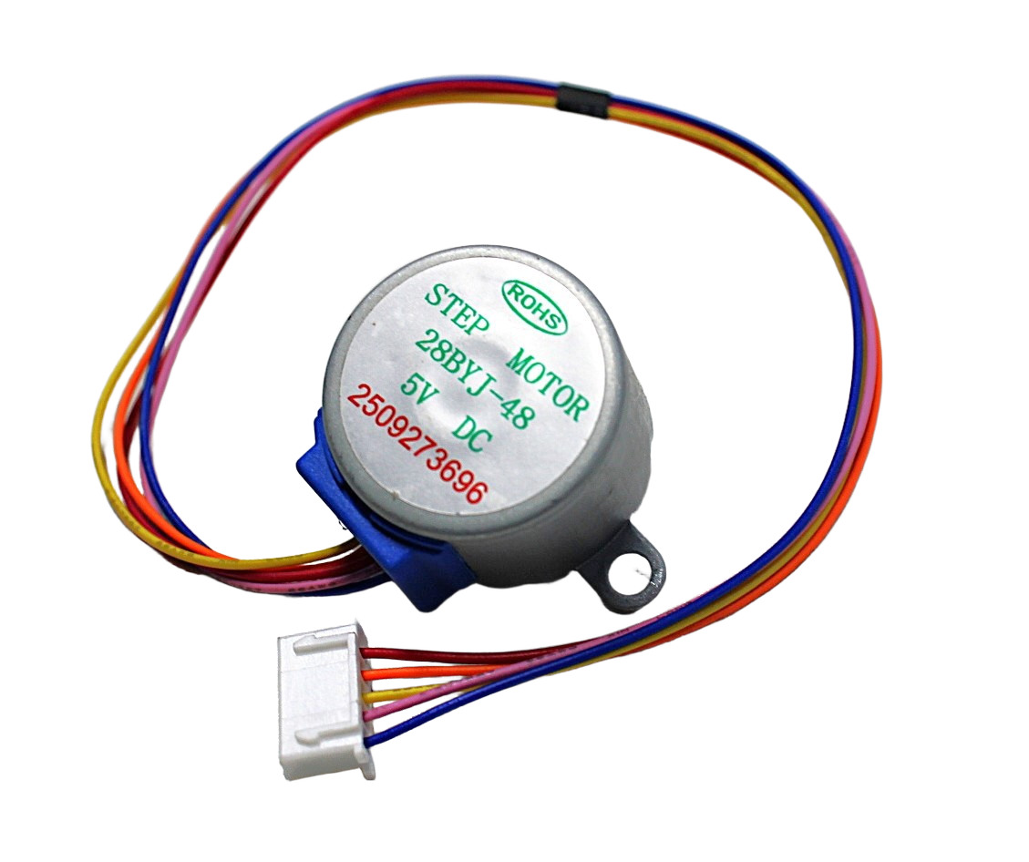
28BYJ-48 5V Stepper Motor
Affordable beginner stepper motor for learning basic stepper control before stepping up to NEMA 17/23 motors with the TB6600.
Frequently Asked Questions
Q: Can I power the TB6600 from a 12V adapter?
Yes, 12V works but is suboptimal for NEMA 23 motors. At 12V, you will notice significant torque reduction at speeds above 300 RPM. For NEMA 17 motors in non-demanding applications, 12V is fine. For CNC applications, use 24V or higher for the best performance.
Q: Why does my motor get very hot even at low speeds?
At standstill, a stepper motor dissipates full rated current as heat in the coils. This is normal to some extent, but if it is too hot to touch, your current setting is too high. Reduce the DIP switch setting by one step. You can also add an idle-current reduction feature in your firmware — disable the driver (ENA LOW) when the motor has not moved for 2 seconds.
Q: What power supply should I use for TB6600 with a NEMA 23 motor?
For a single NEMA 23 at 3A, use a 24V 5A power supply. For a CNC machine with three axes, use a 24V 15A or 36V 10A supply. Always size the PSU at least 20% above your calculated maximum current draw.
Q: The TB6600 gets hot during operation. Is this normal?
Some warmth is normal — the aluminium housing is a heatsink. If it becomes uncomfortably hot (over 60°C), reduce the current DIP switch setting or improve airflow in your enclosure. The TB6600 has over-temperature protection that will shut it down if it gets dangerously hot.
Q: Can I use the TB6600 with a Raspberry Pi?
Yes. The TB6600 accepts 3.3V logic signals, which is the GPIO voltage of the Raspberry Pi. Connect PUL+ and DIR+ to GPIO pins and PUL- and DIR- to GND. Use Python with the RPi.GPIO library to generate step pulses. For smooth motion, consider using the pigpio library which provides hardware-timed PWM for step pulse generation.
Q: What is the difference between the TB6600 and DM542 drivers?
The DM542 is a more advanced industrial driver that supports up to 4.2A and uses 256-microstep interpolation for even smoother motion. It is also more expensive. For most DIY CNC and 3D printing projects, the TB6600 is more than sufficient. The DM542 is worth considering for professional CNC machines where smoothness and reliability under sustained heavy loads are critical.
Ready to build your CNC or motion control project? The TB6600 stepper motor driver pairs perfectly with NEMA 17 and NEMA 23 motors available at Zbotic.in. Browse our full range of stepper motors, drivers, and motion control components — all delivered across India with fast shipping.


Add comment