
If you have ever tried to analyse an electrical circuit and felt lost staring at a tangle of resistors, voltage sources, and wires, Kirchhoff’s Laws are the two rules that cut through all the confusion. Whether you are a student preparing for board exams, an engineering aspirant, or a hobbyist building your first breadboard project, mastering Kirchhoff’s Voltage Law (KVL) and Kirchhoff’s Current Law (KCL) will transform how you read and design circuits.
In this in-depth guide, we walk through both laws with clear definitions, step-by-step worked examples, and practical tips so you can confidently apply them to real circuits.
What Are Kirchhoff’s Laws?
Gustav Robert Kirchhoff, a German physicist, published these two fundamental laws in 1845. They are rooted in two conservation principles that govern all electromagnetic circuits:
- Kirchhoff’s Current Law (KCL) — based on conservation of electric charge
- Kirchhoff’s Voltage Law (KVL) — based on conservation of energy
Together, they allow you to write a system of equations for any linear circuit, no matter how complex, and solve for unknown voltages and currents. They work for DC circuits, AC circuits (using phasors), and even in SPICE simulations.
Kirchhoff’s Current Law (KCL) Explained
The Statement
The algebraic sum of all currents entering and leaving a node (junction) is zero.
In plain language: whatever current flows into a junction must also flow out of it. Charge cannot accumulate at a node in a DC steady-state circuit.
Mathematically:
ΣI_in = ΣI_out
or equivalently
ΣI = 0 (sum at a node)
Sign Convention
You can choose any sign convention, but you must be consistent throughout one problem:
- Currents entering a node → positive (+)
- Currents leaving a node → negative (−)
KCL Practical Examples
Example 1 — Simple Three-Branch Node
Consider a node where three wires meet. The currents are:
- I₁ = 3 A entering the node
- I₂ = 1 A entering the node
- I₃ = ? leaving the node
Applying KCL:
I₁ + I₂ = I₃
3 + 1 = I₃
I₃ = 4 A
So 4 A leaves the node, which satisfies charge conservation perfectly.
Example 2 — Four-Branch Node
Suppose you have four branches at a node with the following known values:
- I₁ = 5 A (in)
- I₂ = 2 A (out)
- I₃ = 3 A (out)
- I₄ = ? (direction unknown)
Using KCL:
I₁ − I₂ − I₃ + I₄ = 0
5 − 2 − 3 + I₄ = 0
I₄ = 0 A
Interesting result — zero current in that fourth branch, meaning it could be an open circuit or two equal and opposite sources that cancel out.
Example 3 — Parallel Resistor Network
Two resistors in parallel: R₁ = 10 Ω and R₂ = 20 Ω connected across a 12 V supply. Total current I_T flows in from the supply.
I₁ = V/R₁ = 12/10 = 1.2 A
I₂ = V/R₂ = 12/20 = 0.6 A
KCL at top node: I_T = I₁ + I₂ = 1.2 + 0.6 = 1.8 A
This matches what you would get directly from the equivalent parallel resistance (R_eq = 6.67 Ω, I_T = 12/6.67 = 1.8 A), confirming KCL.
Kirchhoff’s Voltage Law (KVL) Explained
The Statement
The algebraic sum of all voltages around any closed loop in a circuit is zero.
Practically: as you travel around a closed loop, the energy you gain from voltage sources is exactly equal to the energy you lose across resistors and other loads.
ΣV = 0 (around any closed loop)
Sign Convention for KVL
Walk around the loop in one chosen direction (clockwise or counter-clockwise — pick one and stick with it):
- If you enter a resistor at the terminal where current enters → voltage drop → write −IR
- If you enter a voltage source at its negative terminal → you gain voltage → write +V_s
- If you enter a voltage source at its positive terminal → you lose voltage → write −V_s
KVL Practical Examples
Example 1 — Single Loop Series Circuit
A 9 V battery, R₁ = 100 Ω, R₂ = 200 Ω connected in series. Find the current I.
Going clockwise around the loop:
+9 − I×100 − I×200 = 0
9 = 300I
I = 9/300 = 0.03 A = 30 mA
Now verify voltages:
V_R1 = 0.03 × 100 = 3 V
V_R2 = 0.03 × 200 = 6 V
Check: 3 + 6 = 9 V ✓
Example 2 — Two-Loop Circuit (Mesh Analysis)
Consider a circuit with:
- V₁ = 10 V (left source)
- V₂ = 5 V (right source)
- R₁ = 2 Ω (left branch)
- R₂ = 4 Ω (middle branch)
- R₃ = 3 Ω (right branch)
Define mesh currents I₁ (left loop, clockwise) and I₂ (right loop, clockwise).
Loop 1 (KVL):
+10 − 2I₁ − 4(I₁ − I₂) = 0
10 − 2I₁ − 4I₁ + 4I₂ = 0
10 = 6I₁ − 4I₂  ...(1)
Loop 2 (KVL):
−4(I₂ − I₁) − 3I₂ + 5 = 0
5 + 4I₁ − 4I₂ − 3I₂ = 0
5 = −4I₁ + 7I₂  ...(2)
Solving simultaneously:
From (1): 10 = 6I₁ − 4I₂
From (2): 5 = −4I₁ + 7I₂

Multiply (2) by 1.5: 7.5 = −6I₁ + 10.5I₂
Add to (1): 17.5 = 6.5I₂ → I₂ = 2.69 A
Substitute back: I₁ = (10 + 4×2.69)/6 = 3.46 A
Example 3 — Circuit With Multiple Voltage Sources
Two voltage sources V₁ = 12 V and V₂ = 6 V in the same loop with R = 6 Ω. Both sources oppose each other.
KVL: +12 − 6I − 6 = 0
6 = 6I
I = 1 A
The net driving voltage is (12 − 6) = 6 V, which pushes 1 A through 6 Ω. Makes intuitive sense.
Combined KVL + KCL Example
This is where it all comes together. Consider a bridge circuit or a Wheatstone-style network. Rather than brute-force it, you assign node voltages (nodal analysis uses KCL) and loop equations (mesh analysis uses KVL) systematically.
Circuit description:
- 12 V supply between nodes A and D
- R₁ = 3 Ω between A and B
- R₂ = 6 Ω between A and C
- R₃ = 4 Ω between B and D
- R₄ = 2 Ω between C and D
- R₅ = 5 Ω between B and C
Step 1: Set V_D = 0 (reference). V_A = 12 V.
Step 2: Write KCL at node B:
(V_A − V_B)/R₁ = (V_B − V_D)/R₃ + (V_B − V_C)/R₅
(12 − V_B)/3 = V_B/4 + (V_B − V_C)/5
Step 3: Write KCL at node C:
(V_A − V_C)/R₂ = (V_C − V_D)/R₄ + (V_C − V_B)/R₅
(12 − V_C)/6 = V_C/2 + (V_C − V_B)/5
Solving these simultaneous equations (multiply through by LCM = 60) gives the node voltages, from which every branch current can be found using Ohm’s Law — a perfect fusion of KCL, KVL, and Ohm’s Law.

0 Ohm 0.25W Carbon Film Resistor (Pack of 100)
Perfect for breadboard prototyping while practising KVL and KCL experiments — build real circuits and verify your calculations hands-on.
Common Mistakes and How to Avoid Them
- Inconsistent sign convention: Decide on your convention (passive sign or active sign) at the start and never switch mid-problem. Mixing conventions is the single biggest source of errors.
- Forgetting to account for shared branches: In mesh analysis, a resistor shared between two loops carries the difference of the two mesh currents (I₁ − I₂), not just one of them.
- Treating a node as a loop: KCL applies at nodes (junctions); KVL applies around loops. They are different things — do not confuse them.
- Not checking your answer: Always substitute your answers back into the original KCL/KVL equations to verify. If the equations do not balance, there is an arithmetic error somewhere.
- Ignoring internal resistance: Real batteries have internal resistance. Add it as a series resistor in your loop equations for more accurate results.
Real-World Applications
Kirchhoff’s Laws are not just academic exercises — they are used every day by engineers designing products you use:
- PCB design: Circuit simulators like LTspice and KiCad use KCL/KVL (via nodal analysis) to simulate circuits before fabrication.
- Power distribution: Electrical engineers use KCL to balance load currents in multi-branch power grids.
- Amplifier biasing: Designing the bias network of a BJT amplifier requires applying KVL around the base-emitter loop and KCL at the collector node.
- Battery management: BMS circuits use current sensing at nodes — a direct application of KCL — to monitor charge and discharge paths.
- Troubleshooting: When a circuit does not behave as expected, measuring node voltages and checking them against KVL predictions instantly narrows down where a fault lies.

10CM Female To Female Breadboard Jumper Wires 2.54MM – 40Pcs
Connect components on your breadboard to build the series and parallel circuits from the KCL/KVL examples above and measure real currents and voltages.
Tools You Need to Practise
The fastest way to internalise Kirchhoff’s Laws is to build real circuits, measure them, and compare with your calculations. Here is what you need:
- Breadboard: For quick no-solder prototyping of series, parallel, and multi-loop circuits.
- Multimeter: Measure actual node voltages and branch currents and compare with your KVL/KCL answers.
- Resistors: A kit with several values (100 Ω, 200 Ω, 470 Ω, 1 kΩ, etc.) lets you build the exact circuits from the examples above.
- DC power supply: A stable 5 V or 12 V supply gives you known source voltages for controlled experiments.
- Jumper wires: Essential for connecting components on the breadboard.
- Notebook: Draw the circuit before measuring; verify your KCL/KVL equations against actual readings.
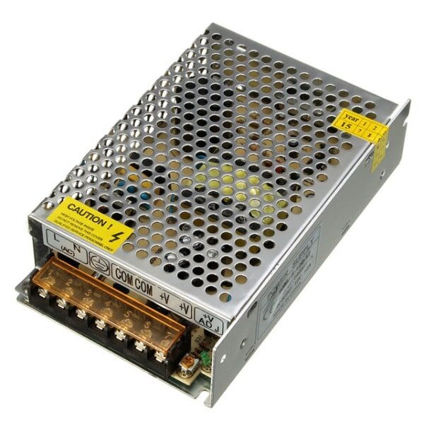
12V 10A SMPS – 120W DC Metal Power Supply
A stable, regulated 12 V DC supply is the ideal voltage source for multi-loop KVL and KCL circuit experiments on your workbench.
Frequently Asked Questions
What is the difference between KCL and KVL?
KCL (Kirchhoff’s Current Law) deals with currents at a node and is based on conservation of charge. KVL (Kirchhoff’s Voltage Law) deals with voltages around a closed loop and is based on conservation of energy. In practice, you often use both together to analyse a circuit fully.
Do Kirchhoff’s Laws work for AC circuits?
Yes. KCL and KVL apply to AC circuits when you use phasor (complex number) representations of voltage and current. The equations look the same, but the quantities are complex phasors rather than real numbers.
What is a node in circuit analysis?
A node is any point in a circuit where two or more circuit elements are connected together. All points along an ideal (zero-resistance) wire are part of the same node.
Can Kirchhoff’s Laws be applied to non-linear circuits?
KCL and KVL always hold — they are conservation laws. However, in non-linear circuits (containing diodes, transistors in non-linear regions), the element relationships are non-linear, making the resulting equations harder to solve (often requiring iterative numerical methods).
How many independent equations can I write using KCL and KVL?
For a circuit with N nodes and B branches: KCL gives (N − 1) independent equations, and KVL gives (B − N + 1) independent equations. Together they always equal B, which is the number of unknowns (branch currents), so you always have a complete solvable system.
What are mesh currents?
Mesh currents are imaginary loop currents assigned to each independent loop (mesh) in a planar circuit. They are a mathematical convenience that automatically satisfies KCL at every node. You then apply KVL to each mesh to find the mesh current values, from which all branch currents are derived.
Why does KVL state the sum of voltages is zero?
Because voltage is defined as work done per unit charge. When you travel around a closed loop and return to the starting point, the net work done must be zero — you cannot gain or lose energy just by going in a circle. This is conservation of energy applied to electric circuits.
Ready to Build and Test Your Own Circuits?
The best way to master Kirchhoff’s Laws is to stop calculating on paper and start measuring on a real circuit. Grab resistors, jumper wires, and a power supply from Zbotic and verify your KVL and KCL equations with actual multimeter readings.


Add comment