
433MHz RF Module: Low Cost Wireless Data Transmission Guide
If you are searching for the perfect 433MHz RF module Arduino tutorial to add wireless communication to your projects without breaking the bank, you have landed in the right place. The 433MHz RF module is arguably the most affordable and beginner-friendly wireless solution available to Indian electronics hobbyists today, costing under ₹50 for a transmitter-receiver pair. In this comprehensive guide, we will walk you through everything — from hardware wiring and library setup to writing your first wireless sketch — so you can start sending data over the air in just a few minutes.
What Is a 433MHz RF Module?
A 433MHz RF (Radio Frequency) module is a simple one-way or two-way radio communication device that operates on the 433.92 MHz ISM (Industrial, Scientific and Medical) band — a license-free frequency in India and most of the world. The typical kit comes as a pair: one small transmitter (TX) board and one receiver (RX) board.
Key specifications you will usually see:
- Operating frequency: 433.92 MHz
- Operating voltage: Transmitter 3–12V, Receiver 5V
- Modulation: ASK (Amplitude Shift Keying) / OOK
- Data rate: Up to 10 kbps
- Range: 20–200 meters depending on antenna and environment
- Price in India: ₹30–₹80 for a TX+RX pair
These modules are ideal for simple one-way telemetry — sending sensor readings from a remote node to a base station, controlling relays wirelessly, building remote weather stations, or triggering actuators from a distance. They are not suitable for two-way acknowledgement-based protocols or high-speed data; for those tasks look at NRF24L01 or ESP-NOW instead.
Components You Need
Before diving into the code, gather the following hardware:
- 433MHz RF Transmitter + Receiver pair (FS1000A / XY-MK-5V or equivalent)
- 2 × Arduino Uno / Nano (one acts as transmitter, one as receiver)
- Jumper wires and breadboard
- A 17.3 cm straight copper wire for antenna on each module (optional but recommended)
- USB cables for both Arduinos
- OLED display or 16×2 LCD for the receiver side (optional for display)
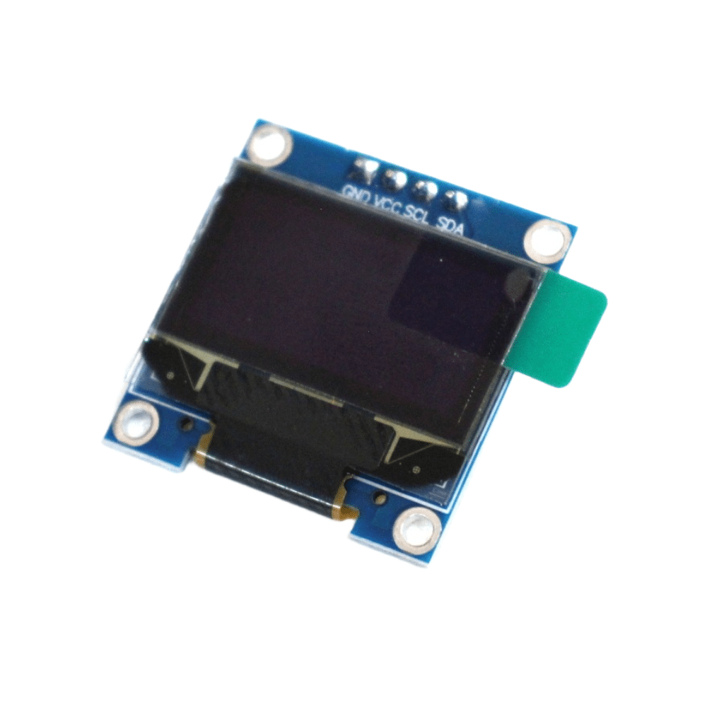
0.96 Inch I2C OLED LCD Module (White, SSD1306)
Display received RF data in real time on this compact OLED screen. Works perfectly with Arduino Uno/Nano over just 2 wires.
Wiring the RF Module to Arduino
Transmitter Side
The FS1000A transmitter has 3 pins: VCC, DATA, GND.
- VCC → Arduino 5V (or use 9–12V for longer range)
- DATA → Arduino Digital Pin 12
- GND → Arduino GND
- ANT → Solder a 17.3 cm wire (quarter-wave antenna for 433MHz)
Receiver Side
The XY-MK-5V receiver typically has 4 pins (two VCC, DATA, GND).
- VCC → Arduino 5V
- DATA → Arduino Digital Pin 11
- GND → Arduino GND
- ANT → Solder a 17.3 cm wire
Pro tip for Indian makers: Electrical noise from SMPS adapters and inverters in Indian homes can wreak havoc on 433MHz reception. Power your receiver Arduino from a USB power bank or laptop USB port for clean 5V and dramatically fewer false triggers.
Installing the RadioHead Library
The RadioHead library by Mike McCauley is the gold standard for 433MHz RF communication with Arduino. It handles Manchester encoding, message framing, and simple CRC checks — far more reliable than raw bit-banging.
Installation steps:
- Open Arduino IDE → Sketch → Include Library → Manage Libraries
- Search for RadioHead
- Click Install on the result by Mike McCauley
- Restart Arduino IDE
The key classes you will use are RH_ASK (for ASK/OOK modules like FS1000A) inside the RH_ASK.h header.
Transmitter Sketch
Upload this sketch to the transmitter Arduino:
#include <RH_ASK.h>
#include <SPI.h> // required by RadioHead

// RH_ASK(speed, rxPin, txPin, pttPin)
RH_ASK driver(2000, 11, 12, 10);

void setup() {
  Serial.begin(9600);
  if (!driver.init())
    Serial.println("RF Init failed");
  else
    Serial.println("RF Transmitter Ready");
}

void loop() {
  const char *msg = "Hello Zbotic!";
  driver.send((uint8_t *)msg, strlen(msg));
  driver.waitPacketSent();
  Serial.println("Message sent");
  delay(1000);
}
You can replace the string "Hello Zbotic!" with any sensor value you want to transmit. To send a number (e.g., a temperature reading), convert it to a char array first using sprintf().
Receiver Sketch
Upload this sketch to the receiver Arduino:
#include <RH_ASK.h>
#include <SPI.h>

RH_ASK driver(2000, 11, 12, 10);

void setup() {
  Serial.begin(9600);
  if (!driver.init())
    Serial.println("RF Init failed");
  else
    Serial.println("RF Receiver Ready");
}

void loop() {
  uint8_t buf[RH_ASK_MAX_MESSAGE_LEN];
  uint8_t buflen = sizeof(buf);

  if (driver.recv(buf, &buflen)) { // Non-blocking
    buf[buflen] = ''; // Null terminate
    Serial.print("Received: ");
    Serial.println((char*)buf);
  }
}
Open the Serial Monitor on the receiver Arduino at 9600 baud. You should see “Received: Hello Zbotic!” appearing every second. If you see nothing, check your antenna wires and ensure both Arduinos share a common GND — a mistake very commonly made by beginners.
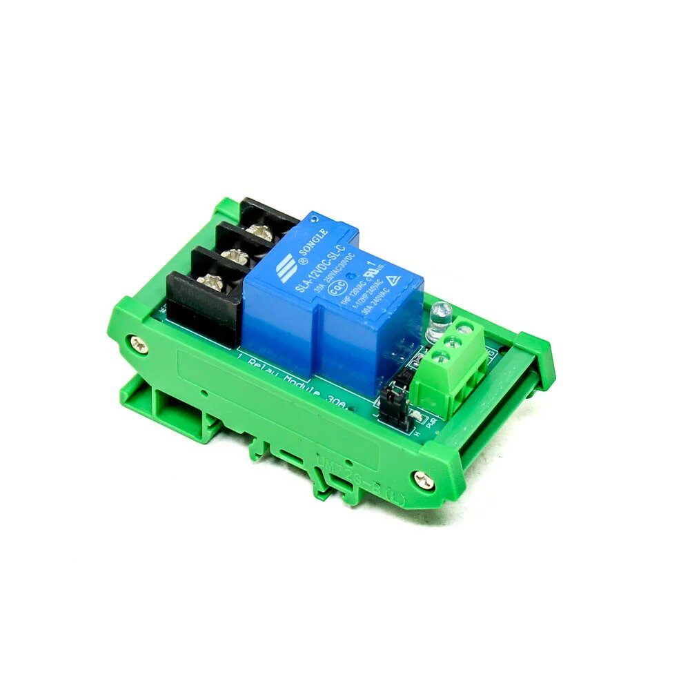
1 Channel 12V 30A Relay Module with Optocoupler
Pair this high-current relay module with the 433MHz receiver to build a wireless switch that controls lights, fans, or motors from 200 metres away.
Extending Range: Antenna & Placement Tips
The default modules ship without any antenna. Following these best practices can push your range from 20 metres to well over 150 metres in open fields — very useful for farm automation and remote monitoring projects common in India.
Antenna Length
For 433.92 MHz, the quarter-wave antenna length is:
λ/4 = 300 / (433.92 × 4) ≈ 17.3 cm
Use a single straight, rigid copper wire of 17.3 cm soldered to the ANT pad. Keep it vertical and away from the PCB ground plane.
Transmitter Voltage
The FS1000A transmitter can handle up to 12V. Powering it from a 9V PP3 battery instead of 5V nearly doubles the output power and doubles the effective range. The receiver always stays at 5V.
Physical Placement
- Keep the transmitter antenna vertical and in the clear — not inside a metal enclosure
- Avoid placing modules near 50Hz AC wiring, motor drivers, and switching regulators
- Elevate both modules for line-of-sight clearance
- Add a 100µF electrolytic capacitor across VCC-GND on the receiver to filter supply noise
Real-World Project Ideas for Indian Makers
Now that you have the basics working, here are some practical project ideas perfectly suited to the Indian hobbyist community:
- Wireless soil moisture monitor: Place a capacitive soil sensor + transmitter Arduino in your terrace garden; receive readings on a base station indoors.
- Remote doorbell system: A momentary button at the gate sends a wireless signal to a buzzer or relay module inside the house.
- Water tank level alert: Ultrasonic sensor at the overhead tank sends fill-level data to a receiver near the kitchen. No Wi-Fi needed.
- Wireless relay control: Control a 12V relay at 100 metres range to switch irrigation pumps or outdoor lights.
- Multi-sensor telemetry: Use a simple protocol byte to multiplex temperature, humidity, and LDR readings from one transmitter node.
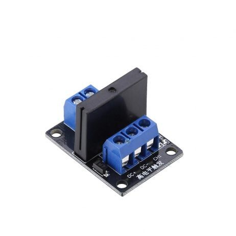
1 Channel 12V Solid State Relay Module (High Level SSR)
Silent, spark-free switching ideal for AC loads. Use with the 433MHz receiver for a completely solid-state wireless switch for home automation.
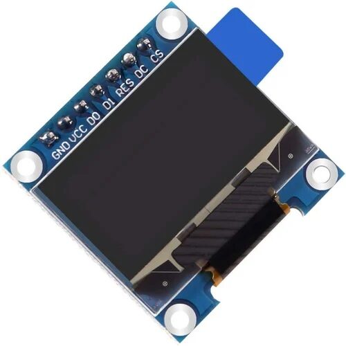
0.96 Inch SPI OLED LCD Module 7pin (White SSD1306)
Fast SPI interface OLED for your receiver display. Show received sensor data, signal strength or status messages in crisp white text.
Frequently Asked Questions
Can I use more than one 433MHz transmitter at the same time?
Yes, but they must not transmit simultaneously or data will collide. Use a TDMA approach: assign each node a fixed time slot to transmit. The RadioHead library does not handle collision avoidance automatically on ASK modules.
Is a 433MHz module legal to use in India?
Yes. The 433–434 MHz band is a license-exempt ISM band in India under WPC rules for low-power devices (under 10 mW EIRP). Hobbyist use with standard FS1000A modules (typically under 1 mW) is completely legal.
Why is my receiver getting garbage data?
The most common causes are: missing antenna wire, no common GND between transmitter and receiver Arduinos, electrical noise from SMPS, or wrong pin numbers in code. Add decoupling capacitors (100µF + 100nF) near the receiver VCC pin and ensure a clean 5V power supply.
What is the maximum data I can send over 433MHz?
RadioHead limits messages to 60 bytes per packet on ASK modules. The practical data rate is around 1–2 kbps at reliable range. For structured data, JSON is too heavy — use a simple comma-separated or binary format instead.
433MHz vs NRF24L01 — which is better for beginners?
433MHz wins on price, simplicity, and range. NRF24L01 wins on two-way communication, speed, and reliability. For first-time wireless projects, start with 433MHz to understand the fundamentals, then graduate to NRF24L01 or ESP-NOW for more capable projects.
Ready to Build Your First Wireless Project?
Zbotic stocks a wide range of RF modules, relay boards, OLED displays, and Arduino boards at the best prices in India — with fast shipping across the country. Build that wireless sensor node today!


Add comment