
The GY-521 MPU6050 is one of the most popular 6-axis inertial measurement units (IMU) used in Arduino projects — covering drones, self-balancing robots, gesture controllers, and more. But straight out of the box, every MPU6050 chip ships with factory offsets that cause your readings to drift even when the sensor is perfectly still. Without proper MPU6050 calibration, your accelerometer may read a non-zero value at rest and your gyroscope will slowly rotate on its own. This tutorial walks you through a complete offset correction procedure so your motion data is rock-solid reliable.
What Is the MPU6050 and Why Does It Need Calibration?
The MPU6050 by InvenSense combines a 3-axis gyroscope and a 3-axis accelerometer on a single chip, communicating over I2C. The GY-521 breakout board adds a voltage regulator, pull-up resistors, and convenient pin headers, making it Arduino-friendly. The chip is incredibly capable — it can measure angular rates up to ±2000 °/s and accelerations up to ±16g — but it has a crucial limitation: each individual chip has unique manufacturing offsets.
These offsets are tiny systematic biases baked into the silicon. When you power the sensor and read raw data with no motion applied, the accelerometer’s Z-axis should read +16384 (for ±2g range, representing 1g of gravity), X and Y should read 0, and all three gyroscope axes should read 0. In practice, you might see the gyroscope reading ±30–200 LSB/s and accelerometer axes off by ±1000 LSB. Over time, this drift causes your angles to wander significantly — a self-balancing robot tips over, a drone drifts sideways, and a gesture controller misreads gestures.
Calibration finds these offsets and programs them directly into the MPU6050’s built-in offset registers. Once written, the chip subtracts them from every reading automatically — no extra CPU overhead, no software corrections cluttering your main loop.
Hardware Setup: GY-521 to Arduino Wiring
Before running any calibration sketch, you need the sensor connected correctly. The GY-521 uses the I2C bus. Here is the standard connection to an Arduino Uno or Nano:
| GY-521 Pin | Arduino Pin | Notes |
|---|---|---|
| VCC | 3.3V or 5V | GY-521 has onboard regulator — 5V safe |
| GND | GND | Common ground |
| SCL | A5 (Uno) / D21 (Mega) | I2C clock |
| SDA | A4 (Uno) / D20 (Mega) | I2C data |
| XDA / XCL | Leave unconnected | For auxiliary I2C devices |
| AD0 | GND (default) | Sets I2C address to 0x68; pull HIGH for 0x69 |
Critical placement tip: During calibration, the sensor must be placed on a perfectly flat, vibration-free surface. Even a table fan in the room or a phone vibrating nearby can corrupt your calibration data. Place the GY-521 component-side up, perfectly level. Use a spirit level if you have one.
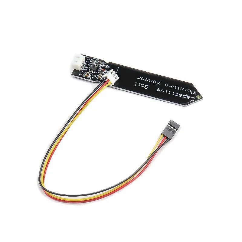
Capacitive Soil Moisture Sensor
Pair sensor modules together for multi-parameter embedded projects — great companion to your MPU6050 builds.
Understanding Gyro and Accelerometer Offsets
The MPU6050 has six dedicated offset registers — one for each axis of each sensor. These registers are 16-bit signed integers stored at addresses 0x06–0x0D (accelerometer) and 0x13–0x18 (gyroscope). Writing to these registers instructs the chip’s internal Digital Motion Processor (DMP) to add the offset value to the raw output of each axis before it reaches you.
Here is the math behind it. Suppose you read the gyro X axis at rest and get a raw value of +85. That means the chip is reporting 85 LSB/s of rotation even though nothing is moving. The full-scale range for ±250 °/s maps to 131 LSB per degree/second, so this bias is roughly 0.65 °/s. After a 60-second flight, that’s 39 degrees of phantom rotation! To correct it, you program the X gyro offset register to -85. The chip subtracts 85 from every reading, and now at rest you read 0.
Accelerometer offsets follow similar logic, except the Z axis at rest must read +8192 (representing 0.5g in ±8g mode) or +16384 (in ±2g mode, representing 1g). You are not trying to zero the accelerometer — you are trying to get it to accurately represent the gravity vector.
A key detail: the offset registers on the MPU6050 use a different scaling factor than the raw data output. Accelerometer offset registers have a resolution of 0.98 mg/LSB regardless of your full-scale setting. Gyro offset registers have a resolution of 0.0305 °/s/LSB regardless of your range setting. Good calibration libraries handle this conversion automatically.
Step-by-Step Calibration Sketch
The easiest and most reliable way to calibrate the MPU6050 is using Luis Ródenas’s calibration sketch, which is widely used in the community. You will need the MPU6050 library by Electronic Cats (available in Arduino Library Manager — search “MPU6050”).
Step 1: Install the Library
Open Arduino IDE → Sketch → Include Library → Manage Libraries. Search for “MPU6050” and install the one by Electronic Cats (version 1.3.0 or later). This installs the IMU_Zero example which serves as our calibration sketch.
Step 2: Load IMU_Zero Example
Go to File → Examples → MPU6050 → IMU_Zero. This sketch averages thousands of readings to find your chip’s unique bias values. Upload it to your Arduino with the GY-521 connected and flat.
Step 3: Run and Record Offsets
Open the Serial Monitor at 115200 baud. The sketch will display lines like:
        XAccel			YAccel			ZAccel			XGyro			YGyro			ZGyro
[-2343,-2342] --> [-14,5]	[-823,-822] --> [-8,1]	[796,797] --> [16385,16386]	[28,29] --> [0,1]	[-23,-22] --> [0,1]	[15,16] --> [-1,0]
...
Offset values:  XA=-2343  YA=-823  ZA=797  XG=28  YG=-23  ZG=15
The sketch runs until all six axes converge to within ±1 LSB of the target (0 for gyro, 0/0/16384 for accel). This typically takes 5–10 minutes. Write down the six offset values.
Step 4: Alternative — Manual Calibration with I2Cdevlib
If you prefer Jeff Rowberg’s I2Cdevlib (the most feature-rich MPU6050 library), use this approach in your setup():
#include <Wire.h>
#include <MPU6050.h>

MPU6050 mpu;

void setup() {
  Serial.begin(115200);
  Wire.begin();
  mpu.initialize();

  // Run calibration — sensor must be still and flat!
  mpu.CalibrateAccel(6);  // 6 iterations (each = 100 readings)
  mpu.CalibrateGyro(6);

  // Print found offsets
  Serial.println("nCalibration complete. Offsets:");
  Serial.print("Accel X: "); Serial.println(mpu.getXAccelOffset());
  Serial.print("Accel Y: "); Serial.println(mpu.getYAccelOffset());
  Serial.print("Accel Z: "); Serial.println(mpu.getZAccelOffset());
  Serial.print("Gyro X:  "); Serial.println(mpu.getXGyroOffset());
  Serial.print("Gyro Y:  "); Serial.println(mpu.getYGyroOffset());
  Serial.print("Gyro Z:  "); Serial.println(mpu.getZGyroOffset());
}
Increasing the iteration count (up to 15) improves accuracy at the cost of time. Six is usually sufficient for most applications.
Applying Offsets to Your Main Sketch
Once you have your six offset values, hardcode them into your main project’s setup() function. This ensures every power cycle starts with a correctly calibrated sensor — no re-calibration needed. Here is how to apply them using I2Cdevlib:
#include <Wire.h>
#include <MPU6050.h>

MPU6050 mpu;

// === YOUR CALIBRATED OFFSETS — replace with your values ===
const int16_t AX_OFF = -2343;
const int16_t AY_OFF = -823;
const int16_t AZ_OFF =  797;
const int16_t GX_OFF =  28;
const int16_t GY_OFF = -23;
const int16_t GZ_OFF =  15;

void setup() {
  Wire.begin();
  Wire.setClock(400000);  // 400kHz fast mode
  Serial.begin(115200);

  mpu.initialize();

  // Apply calibration offsets
  mpu.setXAccelOffset(AX_OFF);
  mpu.setYAccelOffset(AY_OFF);
  mpu.setZAccelOffset(AZ_OFF);
  mpu.setXGyroOffset(GX_OFF);
  mpu.setYGyroOffset(GY_OFF);
  mpu.setZGyroOffset(GZ_OFF);

  Serial.println("MPU6050 ready with calibration offsets applied.");
}

void loop() {
  int16_t ax, ay, az, gx, gy, gz;
  mpu.getMotion6(&ax, &ay, &az, &gx, &gy, &gz);

  // Now ax, ay, az, gx, gy, gz are calibrated values
  Serial.print(ax); Serial.print("t");
  Serial.print(ay); Serial.print("t");
  Serial.println(az);
  delay(50);
}
Important: Offsets are stored in volatile RAM inside the MPU6050. They are NOT saved to flash — you must set them every time the chip powers up. Some developers store offsets in Arduino EEPROM and load them at boot, which is excellent practice for field-deployed devices.
Verifying Calibration Results with Serial Plotter
After applying your offsets, upload the main sketch and open the Arduino Serial Plotter (Tools → Serial Plotter). You should see:
- Gyro axes (GX, GY, GZ): All hovering very close to 0 with only minor noise (±1–3 LSB). No slow drift.
- Accel Z axis (AZ): Stable near +16384 (for ±2g range). This represents the 1g gravitational force pointing down.
- Accel X, Y axes (AX, AY): Stable near 0. Small noise is normal (typically ±50–100 LSB).
If you gently tilt the sensor, the accelerometer axes should respond smoothly and return to their baseline when flat. The gyroscope should show a pulse during the tilt (rotation) and return to zero when stationary — not drift away.
A common mistake is expecting zero noise. The MPU6050 is a MEMS sensor — it inherently has sensor noise. What calibration eliminates is systematic bias (constant offset). Random noise requires filtering, which leads us to complementary filters and Kalman filters — the next level of MPU6050 integration.
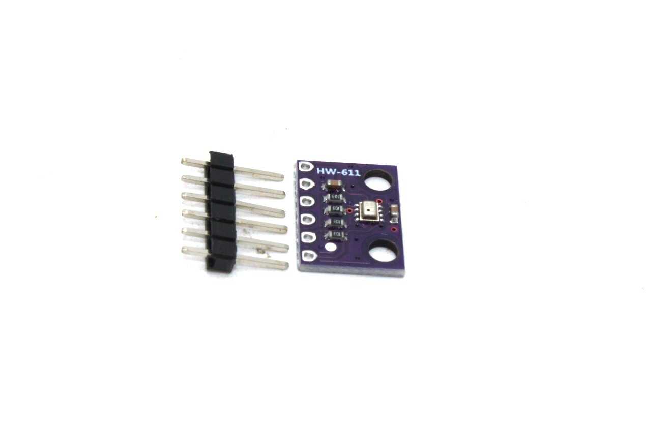
BMP280 Barometric Pressure and Altitude Sensor I2C/SPI Module
Complement your MPU6050 with BMP280 altitude sensing for complete drone flight controller builds using I2C.
Pro Tips for Stable Readings
1. Warm Up the Sensor First
Temperature significantly affects IMU readings. The MPU6050 has a built-in temperature sensor — its readings shift as the chip warms up from ambient to operating temperature. Let the sensor run for 2–3 minutes after power-on before trusting your readings for critical applications. For drone flight controllers, a pre-arm warm-up routine is standard practice.
2. Use 400kHz I2C for Speed
The default Wire library runs at 100kHz. Call Wire.setClock(400000) before initializing the MPU6050 to enable 400kHz fast mode. This reduces data read latency from ~3.5ms to under 1ms, which matters for fast PID control loops running at 1kHz or higher.
3. Re-Calibrate After Mechanical Changes
If you re-mount the GY-521 on a new PCB or chassis, re-calibrate. The stress from soldering or screw mounting can slightly shift the MEMS structure. Also re-calibrate if your readings suddenly worsen after a crash or drop.
4. Use Low-Pass Filtering for Vibration
The MPU6050 has a built-in Digital Low-Pass Filter (DLPF). Set it using mpu.setDLPFMode(MPU6050_DLPF_BW_42) for a 42Hz cutoff, which dramatically reduces high-frequency motor vibration noise in drone applications. Available settings: 260Hz, 184Hz, 94Hz, 44Hz, 21Hz, 10Hz, 5Hz.
5. Decouple Power Supply
Add a 100nF ceramic capacitor close to the VCC and GND pins of the GY-521 to filter power supply noise. Motor drivers, LCD backlight PWM, and servo signals can all inject noise into your 5V rail, destabilizing IMU readings.
6. Store Offsets in EEPROM
#include <EEPROM.h>

// Save offsets after calibration
void saveOffsets(int16_t ax, int16_t ay, int16_t az,
                 int16_t gx, int16_t gy, int16_t gz) {
  EEPROM.put(0,  ax);
  EEPROM.put(2,  ay);
  EEPROM.put(4,  az);
  EEPROM.put(6,  gx);
  EEPROM.put(8,  gy);
  EEPROM.put(10, gz);
}

// Load offsets at boot
void loadOffsets(MPU6050 &mpu) {
  int16_t ax, ay, az, gx, gy, gz;
  EEPROM.get(0,  ax); EEPROM.get(2,  ay); EEPROM.get(4,  az);
  EEPROM.get(6,  gx); EEPROM.get(8,  gy); EEPROM.get(10, gz);
  mpu.setXAccelOffset(ax); mpu.setYAccelOffset(ay); mpu.setZAccelOffset(az);
  mpu.setXGyroOffset(gx);  mpu.setYGyroOffset(gy);  mpu.setZGyroOffset(gz);
}
Frequently Asked Questions
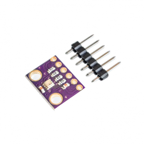
GY-BME280-3.3 Precision Altimeter Atmospheric Pressure Sensor Module
Add altitude and humidity sensing to your flight controller alongside the MPU6050 via shared I2C bus.
Conclusion
Proper GY-521 MPU6050 calibration is the single most impactful step you can take to improve your motion sensing projects. A ten-minute calibration session — finding your chip’s unique accelerometer and gyroscope offsets and loading them at every boot — transforms an erratic, drifting sensor into a reliable, stable one. Whether you are building a self-balancing robot, a drone flight controller, or a gesture-controlled device, calibrated offsets are the foundation everything else is built on.
Once your MPU6050 is properly calibrated, the next step is implementing a complementary filter or Madgwick filter to fuse accelerometer and gyroscope data into clean, drift-free Euler angles. But that is a tutorial for another day — start with calibration and your results will immediately speak for themselves.


Add comment