
ESP32 troubleshooting boot loop brownout flash errors are among the most frustrating experiences for IoT developers and hobbyists across India. You upload your sketch, open Serial Monitor, and see a wall of error text followed by an endless reset loop. Or your project runs fine on USB power but crashes when you switch to a battery. This comprehensive guide covers every common ESP32 failure mode — boot loops, brownout detector resets, flash corruption, Guru Meditation errors, and more — with practical, step-by-step fixes you can apply right now.
Step 1: Reading the Reset Reason from Serial Output
Before attempting any fix, you need to know why your ESP32 is resetting. Open Arduino Serial Monitor at 115200 baud immediately after pressing EN (reset). The first few lines printed at startup contain the most critical information:
ets Jun  8 2016 00:22:57

rst:0x1 (POWERON_RESET),boot:0x13 (SPI_FAST_FLASH_BOOT)
configsip: 0, SPIWP:0xee
clk_drv:0x00,q_drv:0x00,d_drv:0x00,cs0_drv:0x00,hd_drv:0x00,wp_drv:0x00
mode:DIO, clock div:2
load:0x3fff0030,len:1344
load:0x40078000,len:13836
load:0x40080400,len:3608
entry 0x400805f0
The most important field is rst:0xN. Here is the complete reset reason lookup table:
| Code | Name | Meaning |
|---|---|---|
0x1 |
POWERON_RESET | Normal power-on — not a problem |
0x3 |
SW_RESET | Software-triggered reset (ESP.restart()) |
0x4 |
OWDT_RESET | Legacy watchdog timer — loop() blocked too long |
0x5 |
DEEPSLEEP_RESET | Woke from deep sleep — normal |
0x7 |
TG0WDT_SYS_RESET | Timer Group 0 watchdog — CPU stall, usually blocking code |
0x8 |
TG1WDT_SYS_RESET | Timer Group 1 watchdog — same as above |
0xC |
RTCWDT_RTC_RESET | RTC watchdog — deep sleep or severe lockup |
0xF |
BROWNOUT_RESET | Voltage dropped below threshold — power issue! |
You can also read the reset reason programmatically in your sketch:
#include "esp_system.h"

void setup() {
  Serial.begin(115200);
  esp_reset_reason_t reason = esp_reset_reason();
  Serial.print("Reset reason: ");
  Serial.println(reason);
  // 1=POWERON, 3=SW, 4=LEGACY_WDT, 5=DEEPSLEEP
  // 6=SDIO, 7=TG0WDT, 8=TG1WDT, 9=RTCWDT
  // 10=INTRUSION, 11=TGWDT_CPU, 12=SW_CPU_RESET
  // 13=RTCWDT_CPU, 14=EXT_CPU, 15=VBAT, 16=BROWNOUT
}
Fixing Brownout Reset (Most Common Issue)
The brownout reset is the single most common ESP32 problem faced by Indian makers, especially when using batteries, cheap USB cables, or when the ESP32 first connects to Wi-Fi (which draws up to 500 mA in peaks).
The Serial output for a brownout looks like:
Brownout detector was triggered

erts Jun  8 2016 00:22:57
rst:0xf (BROWNOUT_RESET),boot:0x13...
Root causes and fixes:
1. Inadequate Power Supply
The ESP32 requires a stable 3.3V supply capable of delivering at least 500 mA continuous (and 600+ mA peaks during Wi-Fi). Many cheap USB power banks cut out during these peaks. Fix: Use a quality USB power supply rated 1A or higher. On battery projects, use a proper LDO or switching regulator with adequate current rating — not just a bare 18650 cell connected directly.
2. Long or Thin USB Cable
A 2-metre cheap USB cable can have 0.5–1Ω resistance per conductor, causing a 0.25–0.5V voltage drop at 500 mA. Fix: Use a quality short USB cable (under 1 metre) rated for power delivery, not just data.
3. Decoupling Capacitors Missing
On bare ESP32 modules not mounted on a development board, add decoupling capacitors: 100µF electrolytic + 100nF ceramic between 3.3V and GND, placed as close to the module as possible. Development boards from reputable manufacturers already include these.
4. Temporary Fix: Disable Brownout Detector
For testing purposes only (not recommended for production), you can disable the hardware brownout detector:
#include "soc/soc.h"
#include "soc/rtc_cntl_reg.h"

void setup() {
  WRITE_PERI_REG(RTC_CNTL_BROWN_OUT_REG, 0); // Disable brownout
  Serial.begin(115200);
  // ... rest of setup
}
Warning: this can allow the ESP32 to operate at voltages where data corruption is possible. Fix the underlying power issue instead.

2 x 18650 Lithium Battery Shield for Arduino, ESP32, ESP8266
This battery shield includes proper voltage regulation and provides stable 5V/3A output, eliminating brownout resets on ESP32 battery-powered projects. A must-have fix for unstable power issues.
Diagnosing Boot Loop: Stack Overflow, Watchdog, Panic
A boot loop means the ESP32 resets before completing setup() or early in loop(). Look for these specific error messages:
Stack Overflow
***ERROR*** A stack overflow in task loop has been detected.Fix: Your task is using too much stack. Common causes: large local arrays allocated on stack, deep recursion, or very long strings. Solutions: (1) Move large buffers to global/static scope. (2) Use heap_caps_malloc() to allocate from heap. (3) Increase the task stack size if using FreeRTOS tasks directly.
Watchdog Timer Reset (Loop blocked)
E (5000) task_wdt: Task watchdog got triggered.
E (5000) task_wdt: - IDLE0 (CPU 0)
E (5000) task_wdt: - IDLE1 (CPU 1)
The watchdog fires when no task calls the idle task for 5 seconds (default timeout). Causes: blocking calls in loop() longer than 5 seconds, infinite loops without delay() or yield(), or a deadlocked mutex. Fix: Add delay(1) or vTaskDelay(1) in any long-running loop to feed the watchdog and give FreeRTOS time to run its idle tasks.
Heap Corruption / Memory Leak
If your ESP32 runs fine for minutes or hours then starts crashing, suspect a memory leak. Monitor with:
Serial.print("Free heap: ");
Serial.println(ESP.getFreeHeap());
// Add this at the start of loop() — if it decreases over time, you have a leak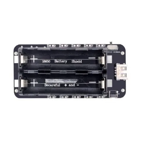
2 x 18650 Lithium Battery Shield V8 for ESP32 ESP8266
The V8 shield provides dual voltage outputs (5V/3A and 3V/1A) for ESP32 projects. Stable regulated power prevents brownout resets and ensures reliable IoT operation on battery.
Fixing Flash Errors and Failed Uploads
Flash-related errors prevent uploading new firmware or cause corruption at startup. Here are the most common error messages and fixes:
“Failed to connect to ESP32: Timed out waiting for packet header”
This is the most common upload error, especially on clone ESP32 boards sold in India. Causes and fixes:
- Not entering download mode: Hold the BOOT/IO0 button while clicking Upload in Arduino IDE. Release BOOT only after the upload starts (you see “Connecting…” stop flashing).
- Wrong COM port: Check Device Manager (Windows) or
ls /dev/ttyUSB*(Linux) after plugging in. - Missing CP2102/CH340 driver: Many Indian market ESP32 boards use CH340G USB-to-serial chip. Download and install the CH340 driver from the official WCH website.
- Bad USB cable: Try a different cable — many cables are charge-only with no data lines.
- Wrong upload speed: Try reducing from 921600 to 115200 baud in Arduino IDE Tools → Upload Speed.
“A fatal error occurred: Failed to write to target RAM”
Usually a power issue during flashing — the flash write current spike causes a brownout. Use a proper power supply during upload and avoid drawing power from other peripherals simultaneously.
Flash erasing and re-programming
If firmware is corrupted and the ESP32 won’t boot at all, use esptool.py to erase the entire flash and reload:
# Install esptool
pip install esptool

# Erase all flash (hold BOOT button while running)
python -m esptool --port COM3 --baud 115200 erase_flash

# Re-upload firmware from Arduino IDE after erase
Decoding Guru Meditation Errors
Guru Meditation is ESP32’s equivalent of a kernel panic. The output looks like:
Guru Meditation Error: Core  1 panic'ed (LoadProhibited). Exception was unhandled.
Core 1 register dump:
PC      : 0x400d2f8a  PS      : 0x00060f30  A0      : 0x800d2f10  A1      : 0x3ffb2f50
...
Backtrace: 0x400d2f8a:0x3ffb2f50 0x400d2f0d:0x3ffb2f70
The most important field is the exception type after “panic’ed”:
- LoadProhibited / StoreProhibited: Null pointer dereference or access to invalid memory address — you are reading/writing a pointer that is NULL or garbage.
- IllegalInstruction: Executing code from a corrupted memory region — usually a stack overflow that overwrote the return address.
- DoubleException: An exception occurred while handling another exception — usually a stack overflow in an ISR.
To decode the backtrace (convert hex addresses to file:line numbers), use the EspExceptionDecoder Arduino IDE plugin or the idf.py monitor command if using ESP-IDF.
Power Supply Best Practices for ESP32
Good power supply design prevents 80% of ESP32 issues. Here is a quick reference for Indian ESP32 projects:
| Power Source | Recommendation | Notes |
|---|---|---|
| USB from PC | Only for development | Limited to 500 mA; some ports cut out at peak Wi-Fi draw |
| 5V USB adapter | Use 1A+ adapter | A good phone charger (like Mi or Redmi) works well |
| 18650 Li-ion battery | Use a battery shield with regulator | Direct connection to ESP32 3.3V pin will cause brownouts as battery discharges |
| Power bank | Use banks rated 2A output | Cheap power banks auto-cut during low-draw periods (sleep mode) |
ESP32 Recovery Mode and Factory Reset
If your ESP32 is stuck in a boot loop and you cannot upload new firmware normally, try these recovery steps:
- Force Download Mode: Hold BOOT button → press and release EN → release BOOT. The chip enters programming mode without executing user code.
- Full Flash Erase: Run
python -m esptool --port COMx erase_flash. This clears all partitions, NVS data, OTA updates, and user code. - Test with a basic sketch: Upload the simplest possible sketch (just Serial.begin + a print) to verify the hardware is working before re-uploading your main project.
- Check for hardware damage: Inspect for shorts, solder bridges, and damaged pins. Use a multimeter to check 3.3V rail voltage during boot.

4 x 18650 Lithium Battery Shield V8/V9 for ESP32 with On-Off Button
For high-demand ESP32 projects with multiple peripherals, this 4-cell shield provides ample current headroom to eliminate brownout resets entirely, with a handy on-off switch.
Frequently Asked Questions
Why does my ESP32 work on USB but crash on battery?
This is almost always a power supply issue. Your USB supply provides regulated 3.3V from the on-board regulator. On battery power, if the battery voltage drops below the regulator’s dropout voltage (typically 4.3–4.5V for common AMS1117 regulators on dev boards), the 3.3V output sags and triggers the brownout detector. Solution: Use a battery pack with a proper boost or buck-boost regulator that maintains stable 3.3V or 5V (for the on-board regulator) across the full battery discharge range.
How do I stop the “Brownout detector was triggered” without disabling it?
Properly fix the power supply: (1) Add a 470µF capacitor across the 3.3V and GND pins on the ESP32 module — this absorbs current spikes during Wi-Fi transmission. (2) Use a quality power source. (3) Reduce the Wi-Fi Tx power: WiFi.setTxPower(WIFI_POWER_11dBm); — reducing from maximum 20 dBm to 11 dBm cuts current draw significantly with minimal range loss in typical indoor Indian home/office environments.
What does “rst:0x10 (RTCWDT_RTC_RESET)” mean?
The RTC watchdog timer fired. This typically happens when the chip is stuck during the boot process itself — either the bootloader is corrupted or there is a hardware fault. Try: (1) Erase the flash completely with esptool. (2) Check that GPIO 0, 2, and 12 are not being held in incorrect states during boot (GPIO 12 must not be HIGH during boot on most ESP32 variants — it changes the flash voltage). (3) Try a different known-good firmware to rule out code issues.
Can I recover an ESP32 that won’t show up on the serial port at all?
If the device does not enumerate as a COM/ttyUSB port: (1) Check the USB cable. (2) Install the correct USB-serial driver (CP2102 or CH340). (3) Try a different USB port or computer. If the device enumerates but won’t boot, hold the BOOT button before connecting USB and keep it held while opening esptool — this forces the serial ROM bootloader to activate regardless of flash contents. If nothing works, the ESP32’s USB-serial chip or the module itself may be damaged.
How do I prevent watchdog resets from my Wi-Fi reconnection code?
Never use a blocking while loop longer than 5 seconds for Wi-Fi connection. Instead, use a timeout-based non-blocking pattern: check WiFi.status() every 500ms, count attempts, and call delay(500) (which yields to the WDT) between checks. If Wi-Fi fails after 20 attempts, log the failure and continue with offline functionality rather than looping forever.
Build More Reliable ESP32 Projects
Get quality ESP32 development boards, battery shields, and power modules at Zbotic. Proper components prevent 80% of brownout and boot-loop issues before they happen. Delivered fast across India.


Add comment