
The ESP32 hall effect sensor is one of the most underused and overlooked features of this popular microcontroller. The ESP32 chip has a built-in hall effect sensor that can detect magnetic fields without any external hardware — a feature unique among popular IoT microcontrollers. In this tutorial, we will explore both the internal hall sensor and external hall effect modules, teach you how to detect magnets, measure motor speed (RPM), detect door open/close events, and build position detection systems — all with an ESP32 and a few inexpensive components.
What is a Hall Effect Sensor?
The Hall effect, discovered by Edwin Hall in 1879, describes what happens when a conductor carrying electric current is placed in a magnetic field perpendicular to the current: a small voltage (the Hall voltage) develops across the conductor at right angles to both the current and the magnetic field. This voltage is proportional to the magnetic field strength.
Modern Hall effect sensors package this principle into integrated circuits that produce a clean digital or analogue output proportional to the magnetic field. They are used everywhere in modern electronics:
- Brushless motor commutation (every BLDC motor uses Hall sensors)
- Automotive wheel speed sensors (ABS systems)
- Smartphone lid/case detection (the flip cover sensor)
- Laptop lid close detection
- Water flow meter pulse counting
- Industrial linear position sensing
- Contactless current measurement
Hall sensors come in two types: latching (output stays after magnet is removed) and non-latching / switch (output follows the magnetic field in real time). For most maker projects, non-latching switch types are used.
ESP32’s Built-in Hall Effect Sensor
The ESP32’s internal hall effect sensor is built directly into the chip die, sandwiched between two pairs of ADC channels (GPIO36 and GPIO39 on ADC1). To use it, you simply call the Arduino hallRead() function — no external components, no wiring:
void setup() {
  Serial.begin(115200);
}

void loop() {
  int hallValue = hallRead();
  Serial.println(hallValue);
  delay(100);
}
Open the Serial Plotter (Ctrl+Shift+L in Arduino IDE) and watch the graph. In the absence of a magnet, the value typically sits between 20–60 (baseline, varies by board). Bring a neodymium magnet close to the ESP32 chip itself (not just any part of the board — the chip is the large black IC) and watch the value change dramatically, typically by 50–200 units depending on magnet strength and orientation.
Limitations of the internal hall sensor:
- Sensitive to the magnetic field at the chip itself — not a remote sensor
- Relatively low sensitivity compared to dedicated hall ICs
- Cannot determine magnetic field direction (north vs south pole)
- Uses ADC1 channels, so readings are affected by the same ADC noise issues
- Not available on all ESP32 variants (ESP32-S2, S3, C3 do NOT have it)
The internal sensor is best suited for detecting whether a magnet is physically attached to or very close to the ESP32 module — a simple but useful feature for tamper detection or case-open detection in sealed devices.
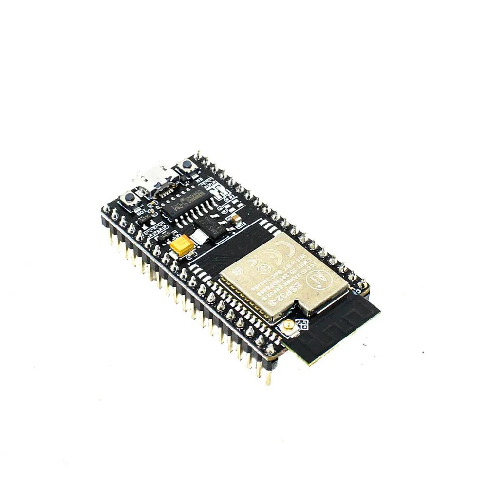
Ai Thinker NodeMCU-32S ESP32 Development Board – IPEX Version
The standard ESP32-WROOM module used in this board contains the original ESP32 chip with the built-in hall effect sensor — perfect for experimenting with all hall effect features.
External Hall Effect Sensor Modules
For practical projects where you need to detect magnets at a distance or measure rotation, external hall effect sensor modules are the right tool. The most common types available in India:
A3144 / OH3144 Hall Effect Switch (Digital)
This is a unipolar switch type — it activates only when the south pole of a magnet is presented to its face. Output is digital (goes LOW when magnet is detected). Used for RPM counters, door sensors, and simple position detection. Operates at 5V but output is logic-compatible with 3.3V systems with a pull-up to 3.3V.
44E / SS49E Linear Hall Sensor (Analogue)
This provides an analogue output proportional to the magnetic field strength. At zero field, the output is approximately half of supply voltage (Vcc/2). South pole increases the output above Vcc/2, while north pole decreases it below Vcc/2. Excellent for contactless position measurement, throttle position sensors, and current sensing.
KY-003 Hall Effect Sensor Module
A convenient breakout module for the A3144, pre-assembled with a pull-up resistor and LED indicator. Plug-and-play for Arduino/ESP32 projects. Widely available in India from electronics shops and online stores.
Wiring External Hall Sensors to ESP32
Wiring external hall sensors to ESP32 is simple. Here are the connections for the most common types:
For A3144 / KY-003 (Digital switch, active LOW):
- VCC → ESP32 3.3V (or 5V if module has level shifter)
- GND → ESP32 GND
- Output → ESP32 GPIO34 (with internal or external pull-up to 3.3V)
Enable internal pull-up in Arduino code: pinMode(34, INPUT_PULLUP);
For SS49E / 44E (Analogue output):
- VCC → ESP32 3.3V
- GND → ESP32 GND
- Output → ESP32 GPIO34 (ADC1_CH6, analogue read)
Important: When powering the SS49E from 3.3V, the quiescent output will be approximately 1.65V (Vcc/2). Stay within ADC1’s linear range by using 0dB or 6dB attenuation for best readings.
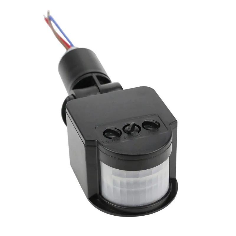
AC 220V Security PIR Human Body Motion Sensor Detector
Combine motion detection with Hall sensor projects for a comprehensive smart security system — detect both intruders and tamper events in one setup.
Code: Magnet Detection and Position Sensing
Here is a complete sketch for magnet detection using a digital hall sensor (A3144 / KY-003), with debouncing and event counting:
#define HALL_PIN 34

volatile bool magnetDetected = false;
volatile unsigned long lastPulseTime = 0;
volatile unsigned long pulseCount = 0;

// Interrupt service routine
void IRAM_ATTR hallISR() {
  unsigned long now = micros();
  if (now - lastPulseTime > 5000) { // 5ms debounce
    magnetDetected = true;
    pulseCount++;
    lastPulseTime = now;
  }
}

void setup() {
  Serial.begin(115200);
  pinMode(HALL_PIN, INPUT_PULLUP); // Sensor output goes LOW when magnet detected
  attachInterrupt(digitalPinToInterrupt(HALL_PIN), hallISR, FALLING);
  Serial.println("Hall sensor ready. Bring a magnet near the sensor.");
}

void loop() {
  if (magnetDetected) {
    magnetDetected = false;
    Serial.printf("Magnet detected! Total pulses: %lun", pulseCount);
  }

  // Print status every second
  static unsigned long lastPrint = 0;
  if (millis() - lastPrint > 1000) {
    lastPrint = millis();
    int state = digitalRead(HALL_PIN);
    Serial.printf("Hall state: %s | Total pulses: %lun",
                  state == LOW ? "MAGNET" : "no magnet",
                  pulseCount);
  }
}
Analogue Hall Sensor for Position Detection
For contactless linear position measurement (e.g., slider position, throttle position), read the SS49E analogue output:
#define HALL_ANA_PIN 34

void setup() {
  Serial.begin(115200);
  analogSetAttenuation(ADC_6db); // 0–2.2V range, better linearity for 0-3.3V signal
}

void loop() {
  // Average 32 readings for noise reduction
  long sum = 0;
  for (int i = 0; i < 32; i++) sum += analogRead(HALL_ANA_PIN);
  int avgADC = sum / 32;
  float voltage = avgADC * (2.2f / 4095.0f);

  // With 3.3V supply, quiescent point ≈ 1.65V → maps to midpoint
  float offset = voltage - 1.1f; // Offset from quiescent (Vcc/2 at 3.3V/2 = 1.65V, but 6dB range is 0-2.2V)
  Serial.printf("ADC: %d | Voltage: %.3fV | Field: %.3fV from centren",
                avgADC, voltage, offset);
  delay(100);
}
Code: Measuring Motor RPM with Hall Sensor
Measuring motor RPM is one of the most popular hall sensor applications. Attach a small neodymium magnet to the motor shaft (or use a magnetic ring), place the hall sensor at a fixed gap (2–5 mm), and count pulses per second:
#define HALL_PIN 34
#define MAGNETS_PER_REVOLUTION 1 // Number of magnets on the shaft

volatile unsigned long pulseCount = 0;
volatile unsigned long lastPulseTime = 0;

void IRAM_ATTR hallISR() {
  unsigned long now = micros();
  if (now - lastPulseTime > 2000) { // 2ms debounce for fast motors
    pulseCount++;
    lastPulseTime = now;
  }
}

void setup() {
  Serial.begin(115200);
  pinMode(HALL_PIN, INPUT_PULLUP);
  attachInterrupt(digitalPinToInterrupt(HALL_PIN), hallISR, FALLING);
}

void loop() {
  static unsigned long lastCalc = 0;
  static unsigned long lastPulseCount = 0;

  if (millis() - lastCalc >= 1000) { // Calculate RPM every second
    unsigned long elapsedTime = millis() - lastCalc;
    unsigned long pulsesDelta = pulseCount - lastPulseCount;

    // RPM = (pulses in period / magnets per rev) * (60000ms / elapsed ms)
    float rpm = ((float)pulsesDelta / MAGNETS_PER_REVOLUTION) *
                (60000.0f / elapsedTime);

    Serial.printf("Pulses: %lu | RPM: %.1fn", pulsesDelta, rpm);

    lastPulseCount = pulseCount;
    lastCalc = millis();
  }
}
For multi-pole motors (e.g., 3-phase BLDC with 7 pole pairs), set MAGNETS_PER_REVOLUTION to the number of electrical cycles per mechanical revolution and adjust your calculation accordingly.
Practical Projects: Door Sensor, Flow Meter, Speedometer
Project 1: Smart Door/Window Sensor
Attach a small magnet to a door and a KY-003 hall sensor to the door frame. When the door closes, the magnet comes within range and the sensor output goes LOW. Use this to trigger:
- An MQTT message to Home Assistant
- A notification to your phone via Firebase Cloud Messaging
- An alarm buzzer for security
- An LED strip that turns on when you enter a room
Project 2: Water Flow Meter (Pulse Counter)
Commercial water flow meters contain a turbine with an embedded magnet and a built-in hall sensor. The output is a pulse train where each pulse represents a fixed volume (typically 1–10 mL per pulse). Connect this to ESP32’s interrupt input and count pulses to measure total water consumption — useful for Indian households monitoring water usage or small agricultural irrigation systems.
Project 3: Bicycle Speedometer
Mount a magnet on a bicycle wheel spoke and attach a hall sensor to the fork. Measure the time between pulses and calculate speed from wheel circumference. Display on an OLED and log to Firebase for tracking your daily rides.
Project 4: Tamper Detection (Using Internal Hall Sensor)
Embed a magnet inside a product casing. The ESP32 inside uses hallRead() to continuously monitor for the magnet. If the casing is opened, the magnet moves away and the hall reading changes — triggering an alert. This is a common technique in IoT device security.

Ai Thinker ESP32-C3-01M Wi-Fi + BLE Module
A compact ESP32-C3 module ideal for embedding in small hall sensor projects like door sensors and tamper detectors where space is at a premium.

4 x 18650 Lithium Battery Shield V8/V9 for ESP32 with On-Off Button
Power your portable hall sensor projects like bicycle speedometers or flow meters with this large capacity 4-cell battery shield for long-running operation.
Frequently Asked Questions
Does the ESP32’s internal hall sensor work on all ESP32 variants?
No. The built-in hall effect sensor is only available on the original ESP32 (Xtensa dual-core, with module names like ESP32-WROOM-32, ESP32-WROVER). The newer variants — ESP32-S2, ESP32-S3, ESP32-C3, ESP32-C6, and ESP32-H2 — do NOT have the internal hall sensor. For these chips, you must use an external hall effect sensor module. The hallRead() function will not be available on these variants.
What type of magnet works best with hall effect sensors?
Neodymium (NdFeB) magnets give the strongest field for their size and are ideal for hall sensor projects. For door sensors, a small 10×5 mm disc magnet is sufficient. For motor RPM sensing, any neodymium magnet that can be glued to the shaft works. Ferrite magnets also work but need to be larger or placed closer to the sensor to produce the same effect.
How close does the magnet need to be to trigger a hall sensor?
This depends on the sensor’s sensitivity and the magnet’s strength. A typical A3144 hall switch with a standard 10 mm neodymium disc magnet will trigger at 5–15 mm. For the ESP32’s internal hall sensor, you typically need the magnet within 10–20 mm of the chip itself. The SS49E analogue sensor can detect weaker fields at greater distances but gives a proportional output rather than a binary trigger.
Can I measure magnetic field strength (Gauss or Tesla) with an ESP32?
Not directly with the internal hall sensor (it lacks calibration data for absolute field measurements). With the SS49E analogue sensor and known calibration, you can estimate relative field strength. For accurate Gauss measurements, use a dedicated IC like the DRV5055 or a 3-axis digital magnetometer like the QMC5883L over I2C, which provides calibrated field measurements in all three axes.
My RPM counter shows fluctuating values. How do I stabilise it?
Ensure the magnet gap is consistent (2–5 mm is ideal). Add debounce filtering in the ISR (minimum pulse interval check as shown in the code above). Make sure the magnet is well-secured on the rotating shaft with no wobble. Also check that the sensor is mechanically stable — any vibration causes false triggers. For very high speed motors (above 10,000 RPM), reduce debounce time accordingly (e.g. 500 microseconds for 10,000 RPM with a single magnet).
Explore More ESP32 Projects at Zbotic
Get ESP32 modules, sensor kits, battery shields, and all the components you need for your next hall sensor project from Zbotic. We are India’s trusted source for genuine electronics components with fast delivery nationwide.


Add comment