
The 7-segment display is one of the most recognisable components in electronics — found in digital clocks, calculators, multimeters, elevator indicators, petrol pump meters, and appliance panels all across India. Despite the proliferation of OLED and TFT screens, 7-segment displays remain the go-to choice when you need bright, visible numeric output at low cost. This comprehensive tutorial explains how 7-segment displays work, the critical difference between common cathode and common anode types, how to wire them to an Arduino or microcontroller, and how to implement multiplexing for multi-digit displays.
What Is a 7-Segment Display?
A 7-segment display is an electronic display device that consists of seven individual LED segments arranged in a figure-8 pattern. By selectively illuminating combinations of these segments, you can display the digits 0–9 and several letters (A, b, C, d, E, F, H, L, P, U, etc.). An optional eighth segment forms the decimal point (DP).
The display is typically housed in a rectangular package with the digit pattern visible through a diffuse red, green, blue, or yellow lens. Standard sizes available in India range from 0.28 inch (7mm) to 4 inch (100mm) for large-format displays. Common package sizes used in hobbyist projects are 0.56 inch and 0.8 inch.
Despite their simple appearance, 7-segment displays require understanding of LED polarity, current limiting, and — critically — whether your specific display is common cathode or common anode. Getting this wrong is the most frequent mistake beginners make.
Segment Naming and Pinout
The seven segments are labelled A through G in a standardised convention:
- A — top horizontal bar
- B — top-right vertical bar
- C — bottom-right vertical bar
- D — bottom horizontal bar
- E — bottom-left vertical bar
- F — top-left vertical bar
- G — middle horizontal bar
- DP — decimal point (optional eighth LED)
The digit 0 uses segments A, B, C, D, E, F (all except G). The digit 1 uses only B and C. The digit 8 illuminates all seven segments. Here is the full truth table:
| Digit | A | B | C | D | E | F | G |
|---|---|---|---|---|---|---|---|
| 0 | 1 | 1 | 1 | 1 | 1 | 1 | 0 |
| 1 | 0 | 1 | 1 | 0 | 0 | 0 | 0 |
| 2 | 1 | 1 | 0 | 1 | 1 | 0 | 1 |
| 3 | 1 | 1 | 1 | 1 | 0 | 0 | 1 |
| 4 | 0 | 1 | 1 | 0 | 0 | 1 | 1 |
| 5 | 1 | 0 | 1 | 1 | 0 | 1 | 1 |
| 6 | 1 | 0 | 1 | 1 | 1 | 1 | 1 |
| 7 | 1 | 1 | 1 | 0 | 0 | 0 | 0 |
| 8 | 1 | 1 | 1 | 1 | 1 | 1 | 1 |
| 9 | 1 | 1 | 1 | 1 | 0 | 1 | 1 |
A standard single-digit 7-segment display has 10 pins: one pin per segment (A–G + DP) and one or two common pins. The physical pin layout varies by manufacturer, so always consult the datasheet for your specific part number.
Common Cathode Configuration
In a Common Cathode (CC) display, all cathodes (negative terminals) of the individual LED segments are internally connected together and brought out to one (or two) common pin(s). The anodes of each segment are brought out individually.
How to drive it: Connect the common pin(s) to GND. To illuminate a segment, apply a HIGH signal (logic 1, typically 3.3 V or 5 V) through a current-limiting resistor to that segment’s anode pin. Segments are turned ON by driving HIGH and turned OFF by driving LOW.
Example with Arduino (5V):
- Common cathode pin → GND
- Arduino digital pin → 220Ω resistor → segment anode pin
- digitalWrite(pin, HIGH) = segment ON; digitalWrite(pin, LOW) = segment OFF
This is the more intuitive configuration for most beginners because HIGH = ON matches natural logic.
Common Anode Configuration
In a Common Anode (CA) display, all anodes (positive terminals) are tied together and connected to the supply voltage (Vcc). The cathodes of each segment are brought out individually.
How to drive it: Connect the common pin(s) to Vcc (3.3 V or 5 V). To illuminate a segment, drive that segment’s cathode LOW (through a resistor). To turn OFF a segment, drive its cathode HIGH. The logic is inverted compared to common cathode — LOW = ON, HIGH = OFF.
Example with Arduino (5V):
- Common anode pin → 5V (Vcc)
- Arduino digital pin → 220Ω resistor → segment cathode pin
- digitalWrite(pin, LOW) = segment ON; digitalWrite(pin, HIGH) = segment OFF
Common anode displays are preferred in some microcontroller designs because NPN transistors and open-drain outputs naturally sink current (pull LOW), making them a better fit for active-low driving.
Common Cathode vs Common Anode: Key Differences
| Aspect | Common Cathode | Common Anode |
|---|---|---|
| Common pin connects to | GND | Vcc (+5V or +3.3V) |
| Segment ON logic | HIGH (logic 1) | LOW (logic 0) |
| Current direction | MC sources current | MC sinks current |
| Multiplexing transistor | NPN (sinks common) | PNP (sources common) |
| BCD decoder compatible | CD4511, 74LS48 | 74LS47, 7447 |
Important tip: You CANNOT interchange common cathode and common anode displays in the same circuit without changing the wiring and logic. Always identify your display type before building the circuit — check the part number on the datasheet or use a multimeter in diode mode to test which pin is common.
To identify with a multimeter: Set to diode test mode. Connect the positive probe to a pin and the negative to all others in turn. When a segment lights up, the positive probe is at the anode. If ALL segments light up when probing one particular pin, that is the common anode pin. If all segments light up when the negative probe is on one pin, that is the common cathode pin.
Current Limiting Resistors
Every LED segment in a 7-segment display requires a current-limiting resistor to prevent excessive current that would burn out the LED. Never connect an LED segment directly to a logic output without a resistor.
Formula: R = (Vcc − V_LED) / I_LED
- Vcc = supply voltage (5 V for Arduino Uno, 3.3 V for ESP32/STM32)
- V_LED = forward voltage of the segment LED (typically 1.8–2.2 V for red, 2.8–3.2 V for green/blue)
- I_LED = desired current per segment (typically 5–15 mA for standard brightness)
Example: 5 V supply, red segments (V_LED = 2.0 V), 10 mA desired: R = (5 − 2.0) / 0.010 = 300 Ω. Use the nearest standard value: 330 Ω.
For 3.3 V supply: R = (3.3 − 2.0) / 0.010 = 130 Ω. Use 150 Ω or 120 Ω.
You need one resistor per segment pin — that is 7 resistors for a single-digit display (8 if using DP). A common shortcut in multiplexed designs is to put one resistor in the common line, but this causes brightness variation as more segments turn on simultaneously and is generally not recommended for quality designs.
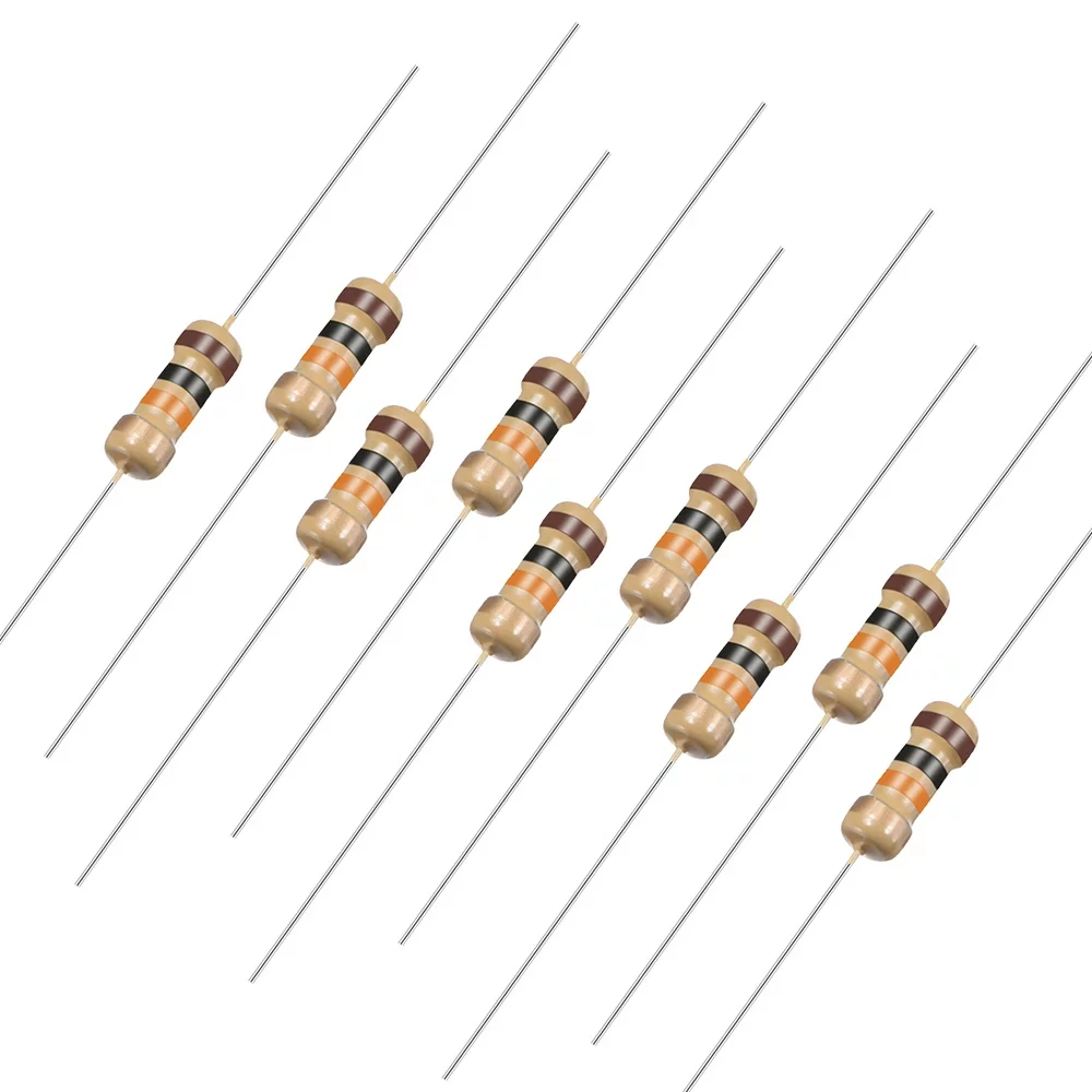
10 Ohm 0.25W Carbon Film Resistor (Pack of 50)
Stock up on resistors for your display projects. 5% tolerance carbon film resistors work perfectly as current limiters for 7-segment display segments.
Wiring to Arduino
Wiring a single common cathode 7-segment display to an Arduino Uno requires 7 digital output pins plus GND. Here is the standard connection:
Display Pin  →  Resistor (330Ω)  →  Arduino Pin
A            →  330Ω             →  D2
B            →  330Ω             →  D3
C            →  330Ω             →  D4
D            →  330Ω             →  D5
E            →  330Ω             →  D6
F            →  330Ω             →  D7
G            →  330Ω             →  D8
Common (-)   →  Direct           →  GND
Here is an Arduino sketch to count 0 to 9 repeatedly:
// Common Cathode 7-Segment Counter
// Segments: A=2, B=3, C=4, D=5, E=6, F=7, G=8

const int segments[] = {2, 3, 4, 5, 6, 7, 8};
// Digit encoding: {A, B, C, D, E, F, G}
const bool digits[10][7] = {
  {1,1,1,1,1,1,0}, // 0
  {0,1,1,0,0,0,0}, // 1
  {1,1,0,1,1,0,1}, // 2
  {1,1,1,1,0,0,1}, // 3
  {0,1,1,0,0,1,1}, // 4
  {1,0,1,1,0,1,1}, // 5
  {1,0,1,1,1,1,1}, // 6
  {1,1,1,0,0,0,0}, // 7
  {1,1,1,1,1,1,1}, // 8
  {1,1,1,1,0,1,1}  // 9
};

void setup() {
  for (int i = 0; i < 7; i++) pinMode(segments[i], OUTPUT);
}

void displayDigit(int num) {
  for (int i = 0; i < 7; i++) digitalWrite(segments[i], digits[num][i]);
}

void loop() {
  for (int d = 0; d <= 9; d++) {
    displayDigit(d);
    delay(1000);
  }
}

10CM Female To Female Breadboard Jumper Wires 2.54MM – 40Pcs
Essential for connecting your 7-segment display module to an Arduino on a breadboard — these 40-piece female-to-female jumpers make prototyping quick and clean.
BCD Decoder ICs: 7447 and 4511
Driving a 7-segment display directly from a microcontroller uses 7 I/O pins per digit. For designs with many digits or limited I/O, BCD (Binary Coded Decimal) decoder ICs reduce this to just 4 data lines per digit.
CD4511 (for Common Cathode)
The CD4511 accepts a 4-bit BCD input (pins A, B, C, D) and drives 7 outputs (a–g) to illuminate the correct segments on a common cathode display. It includes a latch enable (LE), blanking (BL), and lamp test (LT) input. Output current capability: typically 25 mA per segment — enough for direct drive without external resistors in many cases (check datasheet).
74LS47 / 7447 (for Common Anode)
The 74LS47 is the common anode equivalent. Its outputs are active-LOW open-collector, meaning they sink current from the display cathodes. Designed specifically for common anode 7-segment displays. Note that the 74LS47 outputs can display pseudo-characters for inputs A–F, making it useful for hexadecimal display as well.
BCD decoders work excellently in projects like digital clocks, frequency counters, and temperature displays where the number to display is derived from binary arithmetic and you want to minimise microcontroller pin usage.
Multiplexing Multi-Digit Displays
Driving four digits independently would require 4 × 7 = 28 I/O pins plus 4 common lines — 32 pins total, exceeding most microcontrollers. Multiplexing solves this by sharing segment pins across all digits and rapidly switching between digits faster than the eye can detect (persistence of vision).
How Multiplexing Works
- All segment pins (A–G) from all digits are connected in parallel to 7 shared I/O lines.
- Each digit has its own common pin controlled by a transistor or MOSFET (NPN for common cathode; PNP for common anode).
- The microcontroller enables one digit at a time by activating its transistor, sets the segment pattern for that digit, waits for ~2 ms, then moves to the next digit.
- At 4 digits with 2 ms per digit, the complete cycle is 8 ms (125 Hz refresh) — flicker-free to the human eye.
Total pins required for 4-digit multiplexed display: 7 (segments) + 4 (digit selects) = 11 pins. For 8 digits: 7 + 8 = 15 pins. Far better than 64 pins for direct drive.
Multiplexing code tip: Use a timer interrupt (e.g., Timer1 on Arduino) rather than delay() to switch digits. This ensures smooth multiplexing that doesn’t block your main loop.
Driving Displays with MAX7219
For the simplest multi-digit display solution, use the MAX7219 driver IC. This chip communicates over SPI (3 wires: CLK, DIN, CS) and can drive up to 8 digits of 7-segment common cathode displays with no external resistors (one RSET resistor sets brightness). Multiple MAX7219s can be daisy-chained to drive 16, 24, or more digits with just 3 I/O pins.
The popular Arduino library LedControl (by Eberhard Fahle) makes MAX7219 control trivial:
#include <LedControl.h>
// DIN=11, CLK=13, CS=10, 1 device
LedControl lc = LedControl(11, 13, 10, 1);

void setup() {
  lc.shutdown(0, false);  // Wake up
  lc.setIntensity(0, 8);  // Brightness 0-15
  lc.clearDisplay(0);
}

void loop() {
  lc.setDigit(0, 3, 5, false); // Device 0, position 3, digit 5
  delay(1000);
}
The MAX7219 is the go-to solution for Arduino-based clocks, scoreboards, and measurement displays in Indian maker projects.
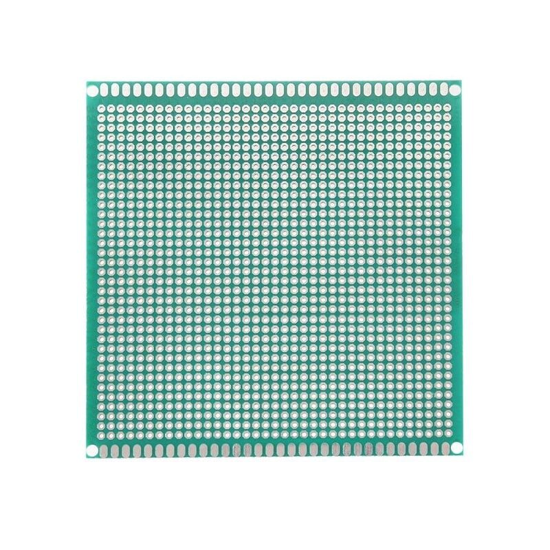
10 x 10 cm Universal PCB Prototype Board Single-Sided 2.54mm Hole Pitch
Build a permanent 7-segment display circuit on this versatile prototype board — 2.54mm pitch fits all standard DIP ICs and through-hole components perfectly.
Frequently Asked Questions
Q1: How do I know if my 7-segment display is common cathode or common anode?
Check the part number printed on the display — most datasheets specify CC or CA in the part number suffix. If you don’t have a datasheet, use a multimeter in diode mode. The pin that causes ALL segments to glow when the positive probe is placed on it is the common anode pin. The pin that causes all segments to glow when the negative probe is on it is the common cathode pin.
Q2: Why are my segments very dim even with the correct wiring?
Most likely, your current-limiting resistors are too high in value. At 5V with a 1kΩ resistor and a red LED (2V forward voltage), current is only 3mA — dim but visible. Try 330Ω or 220Ω for 10mA per segment. Also check that you haven’t accidentally reversed the display (common anode wired as common cathode).
Q3: Can I connect a 7-segment display directly to 3.3V (ESP32, ESP8266)?
Yes, but use smaller resistors. With 3.3V and a red LED (2V Vf), R = (3.3–2.0)/0.010 = 130Ω. Use 120Ω or 150Ω. Also check that the ESP32’s GPIO output current spec (max 12mA per pin, 40mA total) is not exceeded when multiple segments are lit. If driving many segments, use a dedicated driver IC or transistors rather than direct GPIO connection.
Q4: What is the maximum number of digits I can drive with a single Arduino Uno?
Without special driver ICs, multiplexing with an Arduino Uno gives you about 4–6 digits (limited by available pins and refresh rate). With a MAX7219 over SPI, you can drive 8 digits with just 3 pins. Daisy-chaining multiple MAX7219s gives you up to 64 digits with the same 3 SPI wires.
Q5: My display shows segment ghosting during multiplexing. How do I fix it?
Ghosting occurs when residual current lights un-selected segments. Fixes: (1) Add a brief blanking period between digit switches (set all segments LOW for 100µs before enabling next digit). (2) Add pull-down resistors (10kΩ) on segment lines. (3) Ensure transistors switch fast enough — use small-signal transistors (BC547, 2N2222) not slow power transistors. (4) Reduce multiplexing period to keep current pulses short.
Q6: Can I display letters on a 7-segment display?
Yes, limited letters are possible. A (segments A,B,C,E,F,G), b (C,D,E,F,G), C (A,D,E,F), d (B,C,D,E,G), E (A,D,E,F,G), F (A,E,F,G), H (B,C,E,F,G), L (D,E,F), P (A,B,E,F,G), U (B,C,D,E,F) and others. For full alphanumeric display, consider a 14-segment or 16-segment (starburst) display, or an OLED module.
From resistors and jumper wires to prototype PCBs and display driver ICs — Zbotic stocks all the components you need for your 7-segment display and embedded electronics projects, with fast delivery across India.


Add comment