
5V 2A USB Charger Module: Build a Portable Lab Power Supply
Every maker’s workbench needs a reliable 5V power source, and a 5V 2A USB charger module project lets you build one that is portable, rechargeable, and costs a fraction of commercial lab supplies. By combining an 18650 lithium-ion cell (or two in parallel for more capacity) with a boost converter module, a USB charging board, and a protection circuit, you can have a pocket-sized power supply ready for Arduino projects, ESP32 boards, servo testing, and sensor prototyping — anywhere in India, whether you are in a college lab, a makerspace, or working from home. This guide covers the full build from component selection to final assembly.
Project Overview & What You Will Build
This project produces a portable power supply with the following specs:
- Output: 5V DC via USB-A port, capable of 2A continuous
- Input power source: One or two 18650 Li-Ion cells (3.7 V nominal)
- Charging: Micro-USB or USB-C input (depending on module chosen)
- Battery protection: Integrated OVP, UVP, and short-circuit protection
- Display: Optional battery percentage indicator via digital display module
- Runtime: ~3–5 hours at 1A load with two 2500 mAh cells in parallel
The key insight is that a single all-in-one module (like the 18650 dual-USB booster module available at Zbotic) already integrates the boost converter, charger, BMS, and display into one board — drastically reducing build complexity. You only need to add cells, a holder, an on/off switch, and an enclosure.
Components Required & Where to Source
Here is the complete component list for a single-cell build. A dual-cell parallel build just adds a second cell and holder.
| Component | Specification | Qty |
|---|---|---|
| 18650 Li-Ion cell | Genuine 2500–3000 mAh (Samsung 25R or LG HG2) | 1–2 |
| 18650 Battery holder | Single or dual cell, 18.4 mm bore | 1 |
| 5V 2A USB boost/charge module | 3.7V in → 5V/2A out, with display, Micro-USB or Type-C | 1 |
| SPDT or DPDT slide switch | Rated 5A minimum | 1 |
| 22 AWG silicone wire | Red/Black, 300 mm each | — |
| Enclosure | ABS project box ~100×60×25 mm or 3D printed | 1 |
| M2 screws & standoffs | For mounting module inside enclosure | 4 sets |
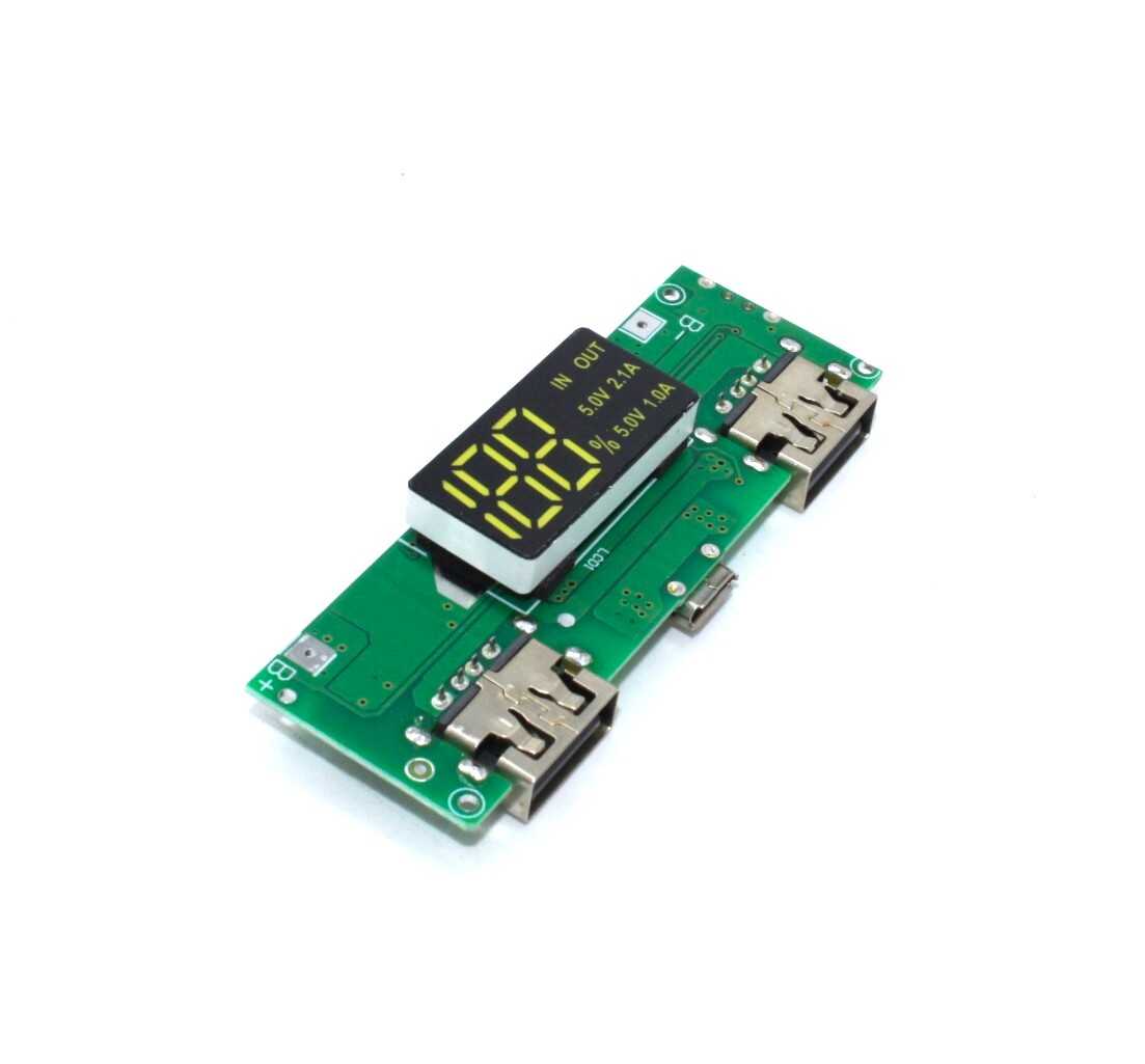
18650 5V 1A/2A Lithium Battery Charging Module with Dual USB & Display
An all-in-one module that integrates the 18650 charger, 5V boost converter, dual USB output, and digital battery percentage display. This single board replaces four separate modules — the heart of this portable lab supply project.
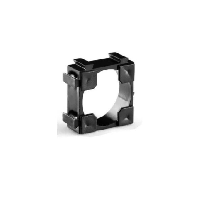
1 x 18650 Battery Holder with 18.4MM Bore Diameter – Pack of 4
Quality battery holders with the correct 18.4 mm bore for standard 18650 cells. Spring contacts ensure low contact resistance. Pack of 4 — use two in parallel for a higher-capacity portable supply build.
Understanding the 5V 2A USB Charger Module
The all-in-one module used in this project is built around two key ICs working in tandem:
The Charger IC
Typically a TP4056 or similar CC/CV linear charger. It accepts 5V from the Micro-USB/Type-C input and charges the connected 18650 cell at up to 1A. The charge indicator LED turns red during charging and green (or turns off) when full. This keeps the cell healthy with proper constant-current / constant-voltage charging profiles.
The Boost Converter IC
A synchronous step-up converter (commonly based on MT3608 or XL6009) boosts the cell voltage from 3.0–4.2 V up to a regulated 5.1–5.2 V output. The slight overvolt (5.1 V) accounts for USB cable resistance drop at 2A — the device sees ≈5.0 V at its connector. The converter efficiency is typically 85–92%, which is why the cell capacity-to-output power ratio is not 1:1.
The Display
A 4-digit 7-segment or bargraph LED display shows battery percentage. It samples the cell voltage and maps it to a 0–100% scale based on the lithium discharge curve. This is an approximation (not Coulomb counting) but is accurate enough for most field use.
Protection Circuit
The integrated BMS section (DW01A + dual N-channel MOSFET) handles over-voltage, under-voltage, and overcurrent protection. Some modules combine charge path and discharge path through separate MOSFETs — check the module datasheet to understand which pins handle charge versus discharge.
Circuit Design & Wiring
The wiring for this project is minimal. Here is the connection schematic in text form:
18650 Cell (+) ──────────────────────────── B+ pad on module
18650 Cell (-) ──────────────────────────── B- pad on module

[Optional] SPDT Switch
Module B+ pad → Switch Common
Switch NO → Battery (+)
(Switches power to module, enabling shutdown)

Output:
Module USB-A port → 5V output to your project
Module Micro-USB/Type-C → Charging input
Important notes on parallel cell wiring: If using two 18650 cells in parallel (for double capacity):
- Match the cells to the same brand, model, and charge level before paralleling. Mismatched cells will try to equalise, causing large equalisation currents.
- Use wire rated for at least 3A (20 AWG minimum) between the cells and module.
- Positive to positive, negative to negative — never mix the rails.
- Both cells must be at the same voltage (within 50 mV) before connecting them together.
Step-by-Step Assembly Guide
- Prepare the cell holder: Solder two short leads (red = positive, black = negative) to the holder terminals. Use 20 AWG wire. Twist the pair together to reduce impedance.
- Insert the cell: Place a genuine 18650 cell into the holder. Confirm polarity by checking voltage across the leads — should be 3.5–4.2 V with red = positive.
- Connect to the module: Solder or clip the cell leads to the B+ and B- pads on the module. The module may briefly show a flash on its display when power is connected — this is normal.
- Add the on/off switch (optional): Insert the switch in series with the B+ wire between the cell holder and the B+ module pad. This cuts all power to the module when off. Alternatively, many modules have a built-in button that toggles the output.
- Plan the enclosure layout: Before closing the enclosure, plan cutouts for: the USB-A output port, the Micro-USB/Type-C charge port, the LED display, the power switch, and ventilation slots (the boost converter generates some heat at 2A).
- Mount the module: Use M2 standoffs or hot glue to secure the module inside the enclosure. Ensure the USB-A port aligns with its cutout and the display is visible through a window.
- Test before closing: With the enclosure still open, connect a USB load (phone, Arduino, USB fan) and verify 5V output. Check that charging works via the charge port.
- Close and label: Close the enclosure. Label the charge port and output port clearly to avoid plugging a load into the charge input.
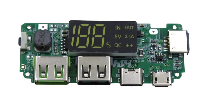
18650 5V 2.4A Lithium Battery Charging Module with Dual USB & Display
Higher-output 2.4A version of the USB boost module — useful when powering a Raspberry Pi (needs 2.5A), larger servo setups, or charging a phone while simultaneously running a test circuit.
Choosing an Enclosure
The enclosure is often the most overlooked part of portable supply projects. Here are your options in India:
- ABS project box: Available at local electronics markets (Lamington Road Mumbai, SP Road Bangalore, Chandni Chowk Delhi). Look for 100×60×25 mm boxes. Pre-drill holes with a 1 mm pilot drill, then file to size for USB ports.
- 3D printed enclosure: Design in FreeCAD or Fusion 360. PLA works for indoor use; PETG is better for field use in hot Indian summers where PLA can warp. Print at 3 walls / 20% infill.
- Recycled enclosure: Old power bank shells (from a dead unit) can house this project perfectly. The form factor and cutouts are already done. Remove the old PCB and fit your new module.
Add a rubber grommet wherever wires pass through enclosure walls to prevent abrasion and shorting.
Testing & Load Verification
Before trusting this supply with your expensive project boards, verify its performance under load:
- No-load output: Measure USB output voltage with a multimeter. Should read 5.0–5.2 V.
- Full-load test: Use a USB load tester (available cheaply online) or connect a 2.5Ω / 10W resistor. At 2A draw, voltage should stay above 4.75 V. If it drops below 4.6 V under 2A, the boost converter is either undersized or the cell has high internal resistance.
- Ripple check: On an oscilloscope, check for voltage ripple on the 5V output. Boost converters typically produce 50–150 mV ripple at switching frequency. For sensitive analog circuits, add a 100µF electrolytic + 100nF ceramic capacitor across the output.
- Temperature check: After 30 minutes at 1.5A load, feel the boost converter IC and the cell holder. The IC should be warm but not hot (under 60°C). The cell should be at or near ambient temperature.
- Runtime test: Measure total runtime at 1A until the UVP kicks in and cuts off output. Divide by 1000 to get mAh delivered (accounting for ~85% converter efficiency).
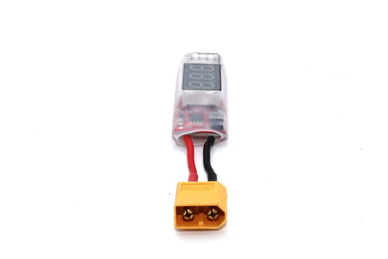
2S-6S LiPo Battery XT60 to USB Adapter with Voltage Display
Tap USB power (5V) from any 2S–6S LiPo pack you already own. Includes a real-time voltage display so you can monitor pack health while powering your bench devices or chargers in the field.
Frequently Asked Questions
Can I charge the battery and power an output device at the same time?
Most all-in-one 18650 boost modules support pass-through charging — yes, you can charge the cell via Micro-USB while simultaneously drawing power from the USB-A output. However, the input current must exceed the output load current, otherwise the cell discharges even while plugged in. For a 2A output load, use a 5V/3A adapter on the charge input to ensure the cell actually charges while in use.
Why does my 5V output drop when I connect an Arduino?
A voltage drop under load usually indicates one of three things: (1) high internal resistance in the 18650 cell (use genuine, low-IR cells), (2) poor contact at the cell holder spring terminals (clean with isopropyl alcohol), or (3) the boost converter is not powerful enough for the connected load. For powering an Arduino with peripherals, ensure the module is rated for at least 1A continuous output.
How long will the battery last powering an Arduino Nano?
An Arduino Nano draws approximately 20–30 mA in active mode. With a 2500 mAh cell and ~85% boost converter efficiency, usable output is about 2125 mAh. At 25 mA draw: 2125 mAh ÷ 25 mA = 85 hours of runtime. With sensors and peripherals attached (say 200 mA total), expect 10–12 hours per charge — more than enough for overnight data logging or field deployments.
Is it safe to leave this power supply on charge overnight?
Yes — if you are using a genuine 18650 cell and a quality module with proper OVP. The TP4056-based charger automatically switches to trickle maintenance mode after reaching 4.2 V. However, always use a genuine cell. Fake cells with no protection can vent or swell even with a good charger. As a general rule, never charge lithium cells unattended in an enclosed space.
Can I use this module to power a Raspberry Pi?
A Raspberry Pi 4 requires 5V at up to 3A (15W) under heavy CPU load. A single-cell 18650 module rated at 2A is borderline — the Pi will work but may show low-voltage warnings during peak usage. For reliable Pi operation from 18650 cells, use a two-cell parallel configuration with a module rated for 2.4A or higher output, or step up to a dedicated PiJuice or PowerBoost 1000C designed for Pi power delivery.
Build Your Portable Lab Supply Today
Zbotic stocks all the modules, holders, and BMS boards you need to build a reliable 5V USB power supply from 18650 cells. Order components and have them delivered across India.


Add comment