
Building a 4-wheeled DIY robot chassis motors Arduino control project is one of the most rewarding entry points into robotics. Whether you are a student, hobbyist, or educator in India, a four-wheeled rover gives you a solid mechanical base to experiment with motor control, sensors, and autonomous logic. This guide walks you through every step — from picking the right chassis to uploading your first motor-control sketch.
Why Choose a 4-Wheel Robot Platform?
A four-wheel robot chassis is the industry standard starting point for ground robots because it offers stability, easy differential steering, and enough surface area to mount electronics. Unlike a 2WD platform that can tip on uneven floors, four wheels distribute weight evenly, making the robot confident on carpets, tiles, and outdoor surfaces alike.
For classroom and competition use in India, the 4WD layout also simplifies PID tuning later — when you are ready to upgrade to line following or maze solving, the motor geometry is already correct. You drive two left-side motors together and two right-side motors together, effectively treating the robot as a two-channel skid-steer vehicle.
Mechanically, acrylic and aluminium chassis kits are inexpensive, lightweight, and easy to drill for custom mounting. They accept standard TT or N20 geared DC motors, which draw modest current and can be driven by an L298N, L293D, or TB6612FNG driver IC — all readily available in India.
Components You Need
Before you start assembling anything, gather the following items. Budget roughly ₹800–₹2,500 depending on whether you buy a complete kit or individual parts.
- Chassis frame — 4-wheel acrylic or aluminium platform with motor mounts
- 4× TT DC geared motors (3V–6V, 1:48 gear ratio typical) + wheels
- Arduino Uno or Nano — the microcontroller brain
- L298N dual H-bridge motor driver module
- 4× AA battery holder (6V) or 2S LiPo pack
- Jumper wires, breadboard, M3 screws, standoffs
- Optional: HC-SR04 ultrasonic sensor, IR line sensors, Bluetooth HC-05 module
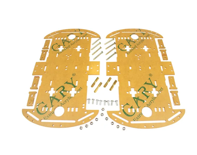
4 Wheels Car Chassis Acrylic Frame
Sturdy acrylic 4WD chassis with motor mounts, encoder discs and hardware. Perfect base for an Arduino robot car project.
Assembling the Chassis and Motors
Most kits come with a double-deck acrylic frame, four TT motors, four wheels, and an assortment of M3 screws. Follow this order:
- Install motors: Slide each TT motor into its bracket on the bottom plate. Secure with M3 bolts — do not over-tighten acrylic. Motor shaft should point outward.
- Attach wheels: Press-fit or screw the plastic wheels onto the motor shafts. Ensure all four wheels sit at the same height to avoid veering.
- Add standoffs: Thread four 30 mm brass standoffs through the corners to support the top plate. The top deck will carry your Arduino, driver module, and battery pack.
- Mount electronics layer: Fix the Arduino and L298N on the top deck using double-sided foam tape or M3 bolts with plastic spacers.
- Route wires neatly: Use zip ties or hook-and-loop strips to keep motor wires along the frame edge so they don’t tangle in the wheels.
When the chassis is assembled, spin each wheel by hand. It should turn freely with only light resistance from the gear train. Stiff wheels indicate a misaligned motor bracket — loosen the screws and reseat.

2WD Mini Round Double-Deck Smart Robot Car Chassis DIY Kit
Compact double-deck chassis kit ideal for beginners — comes with motors, wheels and all mounting hardware ready to assemble.
Wiring the Arduino and Motor Driver
The L298N module has two H-bridge channels. Wire the left-side motors to channel A and the right-side motors to channel B (connect them in parallel within each channel).
| L298N Pin | Arduino Pin | Function |
|---|---|---|
| IN1 | D2 | Left motor direction A |
| IN2 | D3 | Left motor direction B |
| IN3 | D4 | Right motor direction A |
| IN4 | D5 | Right motor direction B |
| ENA | D9 (PWM) | Left motor speed |
| ENB | D10 (PWM) | Right motor speed |
| 12V | Battery + | Motor power supply |
| GND | Battery − and Arduino GND | Common ground |
| 5V out | Arduino 5V (optional) | Power Arduino from driver |
Important: Always connect GND of battery and GND of Arduino together. Failing to share ground is the number one cause of erratic motor behaviour in beginner builds.
Arduino Code for Motor Control
The following sketch demonstrates forward, reverse, left-turn, right-turn, and stop functions. Drop it into the Arduino IDE, select your board, and upload.
// 4WD Robot — Basic Motor Control
// Zbotic.in Tutorial

#define IN1 2
#define IN2 3
#define IN3 4
#define IN4 5
#define ENA 9
#define ENB 10

void setup() {
  pinMode(IN1, OUTPUT); pinMode(IN2, OUTPUT);
  pinMode(IN3, OUTPUT); pinMode(IN4, OUTPUT);
  pinMode(ENA, OUTPUT); pinMode(ENB, OUTPUT);
}

void forward(int spd) {
  analogWrite(ENA, spd); analogWrite(ENB, spd);
  digitalWrite(IN1, HIGH); digitalWrite(IN2, LOW);
  digitalWrite(IN3, HIGH); digitalWrite(IN4, LOW);
}

void reverse(int spd) {
  analogWrite(ENA, spd); analogWrite(ENB, spd);
  digitalWrite(IN1, LOW); digitalWrite(IN2, HIGH);
  digitalWrite(IN3, LOW); digitalWrite(IN4, HIGH);
}

void turnLeft(int spd) {
  analogWrite(ENA, spd); analogWrite(ENB, spd);
  digitalWrite(IN1, LOW); digitalWrite(IN2, HIGH); // Left motors backward
  digitalWrite(IN3, HIGH); digitalWrite(IN4, LOW); // Right motors forward
}

void turnRight(int spd) {
  analogWrite(ENA, spd); analogWrite(ENB, spd);
  digitalWrite(IN1, HIGH); digitalWrite(IN2, LOW); // Left motors forward
  digitalWrite(IN3, LOW); digitalWrite(IN4, HIGH); // Right motors backward
}

void stopMotors() {
  analogWrite(ENA, 0); analogWrite(ENB, 0);
}

void loop() {
  forward(200);  delay(2000);
  stopMotors();  delay(500);
  turnLeft(180); delay(600);
  stopMotors();  delay(500);
  forward(200);  delay(2000);
  reverse(150);  delay(1000);
  stopMotors();  delay(1000);
}
Adjust the speed values (0–255) and delay durations to match your specific motors and battery voltage. Start at speed 150 to avoid wheel slip and increase gradually.
Adding Sensors and Upgrades
Once basic motor control works, the real fun begins. Here are the most popular upgrades for a 4WD robot in India:
Obstacle Avoidance with HC-SR04
Mount an HC-SR04 ultrasonic sensor on the front. Connect Trig to D6 and Echo to D7. Poll the sensor in your loop — if distance drops below 20 cm, call reverse() then turnLeft(). This gives you a basic bump-and-turn obstacle avoidance robot.
Bluetooth Remote Control with HC-05
Wire HC-05 TX→Arduino RX (pin 0) and RX→Arduino TX via a 1kΩ/2kΩ divider. On your phone, install a Bluetooth RC car app. Map ‘F’ to forward(), ‘B’ to reverse(), etc. Now you have a smartphone-controlled robot.
Mecanum Wheels for Omnidirectional Movement
Swap the standard wheels for 60 mm Mecanum wheels. These rollers angled at 45° let the robot strafe sideways and spin in place without turning. You will need four independent motor driver channels and updated code, but the effect is impressive.

60MM-K Mecanum Wheel (Pack of 4) – Black
Set of four 60 mm Mecanum wheels with 6.7 mm coupling. Enables omnidirectional movement for advanced robot platforms.

ACEBOTT ESP32 Tank Robot Car Expansion Pack (QD001–QD004)
Modular expansion pack for ACEBOTT ESP32 robot kits — adds tank tracks, sensors and WiFi control capability.
Common Problems and Fixes
- Robot pulls to one side: Motors from the same batch can have different RPM tolerances. Add speed trim in code — reduce PWM on the faster side by 5–10 points until straight travel is achieved.
- Motors not spinning despite correct wiring: Check ENA and ENB jumpers on L298N. They must be removed (jumpers bridge 5V to enable) and replaced with PWM wires for speed control.
- Arduino resets when motors start: Insufficient current. Add a 100 µF capacitor across battery terminals and ensure motor and Arduino share a solid common ground.
- L298N gets very hot: The module dissipates heat when running motors at full speed for extended periods. Ensure you use 6V for TT motors, not 12V. Attach a small heatsink to the L298N chip.
- Jerky motion at low speeds: TT motors have high static friction. Set a minimum PWM of ~120 and use
millis()-based timing rather thandelay()for smoother control loops.
Frequently Asked Questions
What is the difference between 2WD and 4WD robot chassis?
A 2WD chassis uses two driven wheels (usually rear) with one or two caster wheels for balance. A 4WD chassis drives all four wheels, offering better traction on uneven surfaces and stronger torque. For competitions or outdoor use, 4WD is preferred; for a simple desk robot, 2WD is lighter and cheaper.
Can I use an ESP32 instead of Arduino?
Yes. The ESP32 has more GPIO pins, built-in WiFi and Bluetooth, and is faster than the Arduino Uno. Wire it exactly as you would an Arduino, but note that ESP32 PWM frequency and channel setup differ — use the ledcWrite() API instead of analogWrite().
How long does a 4×AA battery pack last on a 4WD robot?
At moderate speed, four AA alkaline batteries powering TT motors last roughly 45–90 minutes. A 2S LiPo (7.4V, 1800 mAh) with a 5V buck converter for the Arduino extends run time to 2–3 hours and delivers more consistent voltage.
What is a good top speed for a beginner 4WD robot?
TT motors at 6V with a 1:48 gear ratio typically deliver 60–90 RPM, translating to ~25–35 cm/s (about 1 km/h) with 65 mm wheels. This is ideal for indoor learning — fast enough to be interesting, slow enough to debug safely.
Do I need a separate power supply for Arduino and motors?
Not necessarily. The L298N’s onboard 5V regulator can power the Arduino from the motor battery. However, for cleaner operation — especially when adding sensors — a separate small power bank for the Arduino eliminates motor-noise interference on sensor readings.
Ready to build your own 4-wheeled robot? Browse the full range of robot chassis, motor drivers, Arduino boards, and sensors at Zbotic.in – Robotics & DIY. Fast shipping across India with expert support.


Add comment