
Table of Contents
- Introduction: Why Automate Your Water Pump?
- Components Required
- How a Float Sensor Works
- Relay Module Basics for Beginners
- Wiring Diagram: Arduino + Relay + Float Sensor + Pump
- Arduino Code for Automatic Pump Control
- Two-Sensor Logic: Fill and Overflow Protection
- Adding an LCD Status Display
- Safety Tips for Mains-Powered Pumps
- Recommended Products from Zbotic
- Frequently Asked Questions
Introduction: Why Automate Your Water Pump?
In most Indian homes, water pumps run on a fixed schedule or rely on someone manually flipping a switch. The result is either an overflowing overhead tank wasting thousands of litres every month, or a dry tank that leaves the family without water at inconvenient hours. An automatic water pump controller using Arduino, a relay module, and a float sensor solves both problems elegantly and can be built for under ₹500 using readily available components.
This project is also an excellent entry point into practical embedded systems. It teaches you relay control (essential for any high-power switching), float sensor interfacing, debounce logic, and fail-safe design — skills that transfer directly to irrigation systems, aquariums, industrial water management, and chemical tank monitoring.
This guide covers everything from selecting the right pump and float sensor to writing bulletproof Arduino code that handles sensor bounce, pump lockout delays, and a two-sensor overflow prevention system. By the end, you will have a reliable automatic pump controller suitable for home installation or as a demonstration project.
Components Required
- Arduino Uno (or Nano for compact installation)
- 5 V single-channel relay module (optocoupler-isolated recommended)
- 1× or 2× float ball sensors (NO/NC type)
- DC submersible water pump (12 V) or AC pump with relay-switching circuit
- 12 V power supply (for DC pump) or proper AC isolation (for AC pump)
- 10 kΩ resistors (for float sensor pull-up/pull-down)
- Jumper wires, breadboard or PCB
- Optional: 16×2 LCD with I2C module, buzzer for alarms, LED indicators
- Enclosure rated for outdoor/humid environments (IP65 preferred)
How a Float Sensor Works
A float ball sensor is one of the simplest mechanical switches available. Inside the cylindrical body is a magnetic reed switch; the float ball (which rides on the water surface) contains a small magnet. As the water level rises, the ball rises, bringing the magnet closer to the reed switch and either opening or closing the circuit depending on the orientation.
Float sensors come in two configurations:
- Normally Open (NO): Circuit opens when the float is in the low (downward) position and closes when water lifts the float up. Used for high-level detection.
- Normally Closed (NC): Circuit is closed when float is low (normal) and opens when water lifts the float. Used for low-level detection — the pump runs while the circuit is closed (tank low) and stops when the float rises (tank full).
For a basic single-sensor automatic pump: install one NC float sensor at the full-level mark of your overhead tank. When the tank fills to this level, the float rises, opens the circuit, and the Arduino cuts the relay, stopping the pump. When water is consumed and the level drops, the float falls, closes the circuit, and the pump restarts. This is the entire logic of most commercial automatic pump controllers sold in India.
Wire the float sensor between the Arduino digital input pin and ground. Enable the Arduino’s internal pull-up resistor (INPUT_PULLUP) so the pin reads HIGH when the float is low (circuit open, NC contact open = tank full; NC contact closed = tank low → pin pulled low). The logic may feel counter-intuitive at first — work through it carefully with a multimeter before writing code.
Relay Module Basics for Beginners
A relay is an electrically operated switch. When a small control current flows through the coil, it creates a magnetic field that physically moves a contact arm, switching a much larger current path. This isolation between the control circuit (Arduino’s 5 V logic) and the load circuit (12 V pump or 230 V AC pump) is what makes relays essential for pump control.
Relay modules for Arduino typically include:
- The relay itself (rated for a specific voltage and current, e.g., 10 A / 250 VAC)
- A transistor driver circuit so the Arduino pin does not need to source coil current directly
- An optocoupler for electrical isolation between logic and load ground (choose modules with this — it protects the Arduino from mains surges)
- An LED indicator showing relay state
- A flyback diode across the coil to suppress voltage spikes when the relay de-energises
Most 5 V relay modules are active-LOW: writing LOW to the IN pin activates the relay (NC contact opens, NO contact closes). Writing HIGH deactivates it. This active-LOW behaviour can be confusing — double-check your module’s datasheet or test with a multimeter before connecting any load.
Wire the pump to the NO (Normally Open) contact of the relay. This means the pump is off by default (relay de-energised) and only runs when the Arduino actively energises the relay. This is the safe default: if the Arduino resets or loses power, the pump stops automatically.
Wiring Diagram: Arduino + Relay + Float Sensor + Pump
DC Pump Circuit (12 V)
Arduino D7  ────────────── Relay IN
Arduino 5V  ────────────── Relay VCC
Arduino GND ────────────── Relay GND

Float Sensor Wire 1 ────── Arduino D2
Float Sensor Wire 2 ────── Arduino GND
(use INPUT_PULLUP on D2)

Relay COM ──── 12V+ supply
Relay NO  ──── Pump + terminal
Pump -    ──── 12V- (GND)
AC Pump Circuit (230 V — use extreme caution)
Mains Live ──── Relay COM
Relay NO   ──── Pump Live input
Mains Neutral ─ Pump Neutral input
(Earth all metal parts and enclosure)
Warning: Only work with 230 V mains wiring if you are qualified to do so. Mains voltage is lethal. Use a proper relay with sufficient AC rating (at minimum 10 A / 250 VAC), double-insulated wiring, and an RCD (ELCB) on the supply circuit.
Arduino Code for Automatic Pump Control
Basic Single-Sensor Pump Controller
const int RELAY_PIN = 7;
const int FLOAT_PIN = 2;
const unsigned long DEBOUNCE_DELAY = 2000; // 2 seconds debounce
const unsigned long PUMP_MIN_OFF = 30000;  // Minimum 30s off between cycles

bool pumpRunning = false;
unsigned long lastPumpStop = 0;
unsigned long sensorChangeTime = 0;
bool lastSensorState = HIGH;

void setup() {
  pinMode(RELAY_PIN, OUTPUT);
  digitalWrite(RELAY_PIN, HIGH); // Relay inactive (active-LOW module)
  pinMode(FLOAT_PIN, INPUT_PULLUP);
  Serial.begin(9600);
  Serial.println("Pump Controller Ready");
}

void loop() {
  bool sensorNow = digitalRead(FLOAT_PIN);

  // Debounce: only act if state stable for DEBOUNCE_DELAY
  if (sensorNow != lastSensorState) {
    sensorChangeTime = millis();
    lastSensorState = sensorNow;
  }

  if (millis() - sensorChangeTime > DEBOUNCE_DELAY) {
    // LOW = float down = tank not full = pump should run
    // HIGH = float up = tank full = pump should stop
    if (sensorNow == LOW && !pumpRunning) {
      // Check minimum off time
      if (millis() - lastPumpStop > PUMP_MIN_OFF) {
        startPump();
      }
    } else if (sensorNow == HIGH && pumpRunning) {
      stopPump();
    }
  }
}

void startPump() {
  digitalWrite(RELAY_PIN, LOW); // Energise relay
  pumpRunning = true;
  Serial.println("Pump ON");
}

void stopPump() {
  digitalWrite(RELAY_PIN, HIGH); // De-energise relay
  pumpRunning = false;
  lastPumpStop = millis();
  Serial.println("Pump OFF");
}
The 2-second debounce delay prevents the pump from rapidly cycling on/off when the water surface is choppy and the float sensor bounces around the trigger level. The 30-second minimum off time protects the pump motor from thermal damage due to rapid start/stop cycles — most single-phase motors need a cooling period between starts.
Two-Sensor Logic: Fill and Overflow Protection
A two-sensor system is significantly more robust than a single-sensor design. You install one float sensor at the low-level mark (pump starts when tank drops to this level) and a second at the high-level mark (pump stops when tank fills to this level). This creates hysteresis: the pump runs from low-level to high-level and does not restart until the level drops back to the low mark.
const int RELAY_PIN = 7;
const int FLOAT_LOW = 2;   // LOW sensor at bottom of tank
const int FLOAT_HIGH = 3;  // HIGH sensor at top of tank

void setup() {
  pinMode(RELAY_PIN, OUTPUT);
  digitalWrite(RELAY_PIN, HIGH);
  pinMode(FLOAT_LOW, INPUT_PULLUP);
  pinMode(FLOAT_HIGH, INPUT_PULLUP);
}

void loop() {
  bool lowFloat  = digitalRead(FLOAT_LOW);   // LOW = water below sensor (start pump)
  bool highFloat = digitalRead(FLOAT_HIGH);  // LOW = water above sensor (stop pump)

  if (highFloat == LOW) {
    // Tank full — stop pump
    digitalWrite(RELAY_PIN, HIGH);
  } else if (lowFloat == LOW) {
    // Tank low — start pump
    digitalWrite(RELAY_PIN, LOW);
  }
  // If neither: pump keeps its current state (hysteresis)
  delay(500);
}
This two-sensor approach virtually eliminates the chattering problem because the pump has to travel the full distance between sensors before switching again. In a typical 500-litre overhead tank, this might represent 30–60 minutes of filling — far more than enough hysteresis to prevent rapid cycling.
Adding an LCD Status Display
For a polished installation, add a 16×2 LCD with an I2C backpack module. This allows family members to see the pump status and tank level at a glance without needing to access the serial monitor.
#include <Wire.h>
#include <LiquidCrystal_I2C.h>

LiquidCrystal_I2C lcd(0x27, 16, 2);

void setup() {
  lcd.init();
  lcd.backlight();
  lcd.setCursor(0, 0);
  lcd.print("Pump Controller");
  lcd.setCursor(0, 1);
  lcd.print("Initialising...");
  delay(2000);
}

void updateDisplay(bool pumpOn, bool tankFull, bool tankLow) {
  lcd.clear();
  lcd.setCursor(0, 0);
  lcd.print(pumpOn ? "Pump: ON " : "Pump: OFF");
  lcd.setCursor(0, 1);
  if (tankFull)      lcd.print("Tank: FULL      ");
  else if (tankLow)  lcd.print("Tank: LOW       ");
  else               lcd.print("Tank: Filling...");
}
Safety Tips for Mains-Powered Pumps
- Use an ELCB/RCD: Install an Earth Leakage Circuit Breaker on the pump’s mains supply. This protects against electric shock if insulation fails near water.
- Waterproof the enclosure: Use an IP65-rated plastic enclosure for all electronics. Water and humidity will destroy unprotected PCBs within weeks.
- Fuse the load circuit: Add an appropriately rated fuse on the mains Live line going to the relay. If the pump motor jams and draws excessive current, the fuse blows before the relay contacts weld shut.
- Separate logic and power grounds: If using an optocoupler-isolated relay module, keep the Arduino GND and mains/load GND completely separate. Never bridge them.
- Label all wires: Clearly mark Live, Neutral, and Earth wires inside the enclosure. This is critical for safe maintenance later.
- Dry-run protection: Add a water level sensor in the underground sump tank as well. Running the pump dry (no water to pump) burns out the motor rapidly. Stop the pump if the sump is also empty.
Recommended Products from Zbotic
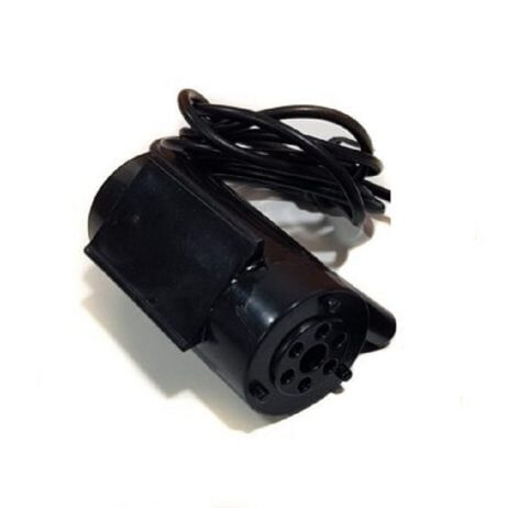
12V High Quality DC Mini Submersible Pump
Compact 12 V submersible pump ideal for Arduino-controlled water projects, aquariums, and small water feature builds. Easy to wire directly through a relay module.
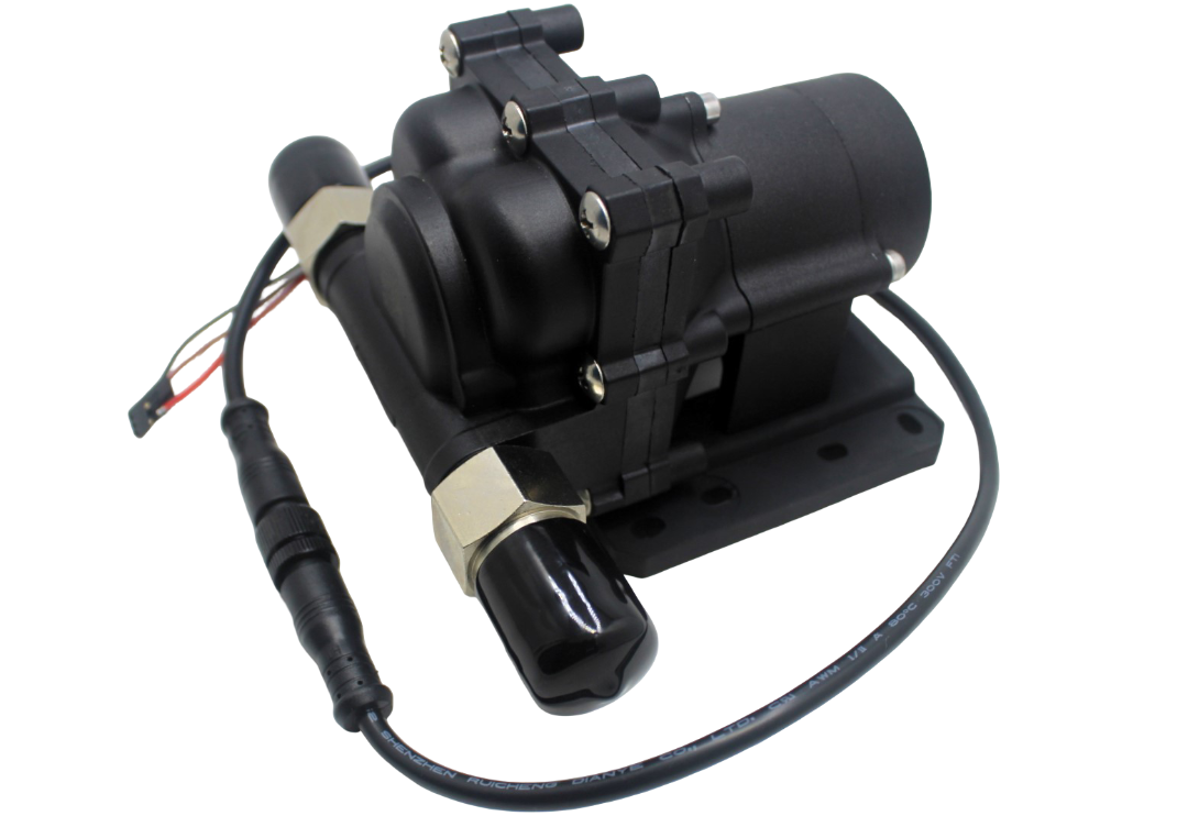
14L Water Pump
Higher-flow 14 L/min pump suitable for larger tanks, irrigation systems, or any application where the mini submersible pump’s flow rate is insufficient.
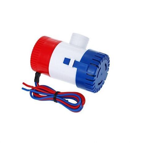
24VDC 350 GPH Bilge Submersible Pump
High-capacity 350 GPH bilge pump for marine, large tank, or industrial water management projects where a relay-controlled high-flow pump is needed.
Frequently Asked Questions
Can I control a 230 V AC pump directly with the Arduino relay module?
Yes, provided your relay module is rated for 230 V AC at the required current (typically 10 A for a 0.5–1 HP household pump). The Arduino only controls the relay coil (5 V DC); the relay’s contacts carry the mains circuit independently. Always use an optocoupler-isolated relay module for mains switching to protect the Arduino from voltage spikes.
My float sensor seems to trigger randomly. What is wrong?
This is almost always caused by a floating (unconnected) input pin or lack of debouncing. Enable the Arduino’s internal pull-up (pinMode(pin, INPUT_PULLUP)) and add a software debounce delay of at least 500 ms to 2 seconds. If the problem persists, add a 100 nF capacitor between the float sensor pin and GND to filter electrical noise.
How do I protect the pump from running dry?
Add a second float sensor in the source tank (underground sump). Wire it so the pump can only run when the sump has water AND the overhead tank needs filling. In code, use an AND condition: if (sumpHasWater && overheadTankNeedsWater) { startPump(); }.
The relay clicks on and off rapidly. How do I fix this?
This is float sensor chatter — the float is hovering right at the trigger level due to water surface movement. Fix with software debounce (wait for stable reading over 2+ seconds) or use a two-sensor system to create mechanical hysteresis.
Can I use an ESP8266 or ESP32 instead of Arduino Uno?
Absolutely. The same wiring and logic applies. ESP8266/ESP32 boards allow you to add Wi-Fi connectivity for remote monitoring via a mobile app or Telegram bot — a common upgrade to this project. Note that ESP boards are 3.3 V logic; most relay modules work fine with 3.3 V input, but verify your specific module’s datasheet.
How long can the Arduino and relay run continuously?
The Arduino Uno is designed for continuous operation — many installations run 24/7 for years. The relay has a rated mechanical and electrical life (typically 100,000 operations). At one pump cycle per day, this is over 273 years of relay life. The weakest point is usually the pump motor and wiring connections, not the electronics.
Build Your Automatic Pump Controller Today
Stop wasting water from overflowing tanks and start saving hundreds of litres every month with a simple Arduino-based pump controller. Zbotic stocks all the components you need — pumps, relay modules, sensors, and Arduino boards — with fast shipping across India.


Add comment