
An ESP32 boot loop fix is something every maker eventually needs. You flash your code, the board restarts, prints a few lines to Serial Monitor, then crashes and restarts again — endlessly. This is one of the most frustrating experiences in ESP32 development, especially because the error messages fly by so fast they are almost impossible to read. This comprehensive guide covers every major cause of ESP32 boot loops, how to diagnose each one using serial output and crash reports, and the exact steps to fix them permanently.
Understanding the ESP32 Boot Process
Before diagnosing a boot loop, you need to understand the normal ESP32 boot sequence. When powered on or reset, the ESP32 runs through these stages:
- ROM bootloader — runs from internal ROM, checks strapping pins (GPIO 0, 2, 5, 12, 15)
- Second-stage bootloader — loaded from flash at offset 0x1000, validates partition table
- Partition table check — at flash offset 0x8000, maps out app and data partitions
- Application loading — loads your sketch from the app0 partition (default 0x10000)
- FreeRTOS kernel start — initializes tasks, WiFi stack, and system services
- app_main() / setup() — your code begins executing
A boot loop can occur at any of these stages. The stage at which the crash happens, combined with the error message, is your primary diagnostic tool. Open your Serial Monitor at 115200 baud immediately after resetting the board — the diagnostic window is narrow (often under 2 seconds before the next restart).
Reading and Decoding the Crash Report
The ESP32’s crash reporter prints a “Guru Meditation Error” with a register dump, followed by a backtrace. Here is a typical crash output:
Guru Meditation Error: Core  1 panic'ed (LoadProhibited).
Exception was unhandled.
Core 1 register dump:
PC      : 0x400d1234  PS      : 0x00060f30
...
Backtrace: 0x400d1234:0x3ffb1e60 0x400d1890:0x3ffb1e80

ELF file SHA256: abc123...

Rebooting...
The key fields to note:
- Panic reason: “LoadProhibited” means a NULL or invalid pointer dereference. “StoreProhibited” means writing to an invalid address. “IllegalInstruction” means corrupted code in flash.
- PC (Program Counter): the address of the failing instruction
- Backtrace addresses: the call stack leading to the crash
To decode the backtrace to actual function names, use the ESP32 Exception Decoder in Arduino IDE (Tools → ESP32 Exception Decoder). Paste the full backtrace and it shows the file and line number of the crash. This single tool resolves 70% of boot loop mysteries.
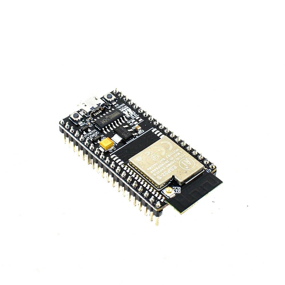
Ai Thinker NodeMCU-32S ESP32 Development Board – IPEX Version
A robust ESP32 board with IPEX antenna connector — reliable for diagnosing boot issues with a clean serial output at 115200 baud.
Top 8 Causes of ESP32 Boot Loops
1. Stack Overflow in Task or setup()
The most common cause. Default Arduino stack for setup() and loop() is 8KB. Large local arrays, recursive functions, or deeply nested JSON parsing easily overflow this. The crash message reads: “Task watchdog got triggered” or “Stack smashing protect failure”.
Fix: Move large arrays to global scope or heap (malloc()). If using FreeRTOS tasks directly, increase the stack size: xTaskCreate(myTask, "Task", 8192, NULL, 1, NULL);
2. Watchdog Timer Timeout (WDT)
The ESP32 has both a task watchdog (TWDT) and an interrupt watchdog (IWDT). If your loop() or any FreeRTOS task runs for more than the watchdog timeout without yielding, the WDT triggers a reset. Common culprits: blocking delays in setup(), large file operations, sensor libraries with internal polling loops, and WiFi operations that hang.
Fix: Add delay(1); or yield(); in tight loops. For long operations, either run them in a separate FreeRTOS task or feed the watchdog manually: esp_task_wdt_reset();
3. Corrupt or Missing Partition Table
If you switch between Arduino IDE boards (e.g., from “ESP32 Dev Module” to “WEMOS LOLIN32”) without erasing flash, the partition tables may conflict. Error message: “partition not found” or “invalid magic byte” in the bootloader output.
Fix: In Arduino IDE: Tools → Erase All Flash Before Sketch Upload → Enabled. Or use esptool.py: esptool.py erase_flash to completely wipe the chip.
4. Wrong GPIO Strapping Pin State at Boot
GPIO 0, 2, 5, 12, and 15 are strapping pins. Their state at boot determines the boot mode and flash voltage. If GPIO 0 is pulled LOW at reset (not by a boot button), the ESP32 enters download mode instead of running your code. If GPIO 12 is HIGH at reset on a 3.3V flash board, it sets the flash voltage to 1.8V, preventing flash reads and causing immediate crashes.
Fix: Ensure GPIO 0 is HIGH during normal operation (the boot button pulls it LOW — do not hold it). Do not connect anything to GPIO 12 that could pull it HIGH at startup. Use the JTAG resistor method to permanently set GPIO 12 if needed.
5. Heap Fragmentation or Out-of-Memory
The ESP32 has ~300KB of free heap for your code after the WiFi/BT stack loads. Frequent malloc()/free() cycles fragment the heap until no contiguous block is large enough for operations like TLS handshakes or JSON parsing. Error: “assert failed: heap_caps_malloc” or “MALLOC_CAP_8BIT” errors.
Fix: Monitor heap with Serial.println(ESP.getFreeHeap()); and ESP.getMinFreeHeap();. Use static allocation where possible. Switch from ArduinoJson DynamicJsonDocument to StaticJsonDocument for fixed-size buffers.
6. WiFi Connection in setup() Without Timeout
A very common beginner mistake: calling while (WiFi.status() != WL_CONNECTED) { delay(500); } with no timeout in setup(). If the router is down or SSID is wrong, this blocks forever and eventually triggers the WDT. The result is an endless boot-connect-crash-reboot cycle.
Fix: Always add a timeout counter. After N attempts, continue without WiFi or restart after a longer delay:
int attempts = 0;
while (WiFi.status() != WL_CONNECTED && attempts < 20) {
  delay(500);
  attempts++;
}
if (WiFi.status() != WL_CONNECTED) {
  Serial.println("WiFi failed — restarting in 10s");
  delay(10000);
  ESP.restart();
}
7. NVS or SPIFFS Corruption
If the ESP32 loses power during a flash write operation, NVS or SPIFFS filesystem can become corrupted. On the next boot, the filesystem mount fails, leading to crashes if your code does not handle the error. Error: “mount failed” or “NVS partition truncated”.
Fix: Format on failure: if (!SPIFFS.begin(true)) { /* formatOnFail=true */ }. For NVS: nvs_flash_erase() followed by nvs_flash_init(). Accept that you will lose stored settings and re-enter them.
8. Library Incompatibility After Update
Updating the ESP32 Arduino core or a library while keeping other libraries at old versions creates API mismatches. The code compiles but crashes at runtime. Always update all ESP32 libraries together or use PlatformIO’s pinned library versions to avoid this.
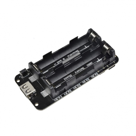
2 x 18650 Lithium Battery Shield for Arduino, ESP32, ESP8266
Power supply issues cause many ESP32 boot loops — this dual 18650 shield ensures stable 5V and 3.3V rails during WiFi transmit peaks.
Hardware-Related Boot Loop Causes
Not all boot loops are software bugs. Hardware problems that cause boot loops include:
Insufficient power supply: ESP32 WiFi transmission peaks draw up to 500mA momentarily. USB ports on computers may be limited to 100mA for unconfigured devices. Cheap USB cables with high resistance cause voltage drops during WiFi transmit. Use a powered USB hub or a dedicated 5V 1A power adapter. The symptom: boot loop disappears when you disconnect sensors and connect only the ESP32.
Brownout detector triggering: The ESP32 has a built-in brownout detector set to ~2.43V. If the 3.3V rail dips below this threshold (even briefly), the brownout detector triggers a reset. You can disable it as a temporary diagnostic measure: esp_sleep_pd_config(ESP_PD_DOMAIN_RTC_PERIPH, ESP_PD_OPTION_OFF); or via the Brownout configuration in menuconfig. Do not leave it disabled in production.
Faulty decoupling capacitors: On cheap clone boards, the bypass capacitors near the ESP32 module may be substandard. Adding a 100µF electrolytic and 100nF ceramic capacitor between 3.3V and GND pins on the board can eliminate brownout-triggered boot loops.
Flash and Partition Issues
If the Serial Monitor shows bootloader output but your sketch never runs, or shows “invalid header” errors, the issue is in flash. Here is the complete flash reset procedure using esptool.py (install with pip install esptool):
# Find your COM port first (e.g., COM3 on Windows, /dev/ttyUSB0 on Linux)
# Hold GPIO 0 LOW while running this command:
python -m esptool --chip esp32 --port /dev/ttyUSB0 erase_flash

# Then reflash with Arduino IDE or:
python -m esptool --chip esp32 --port /dev/ttyUSB0
  write_flash -z 0x1000 bootloader.bin
  0x8000 partitions.bin
  0xe000 boot_app0.bin
  0x10000 sketch.ino.bin
30Pin ESP32 Expansion Board with Type-C USB and Micro USB Dual Interface
Exposes all ESP32 pins cleanly including the boot-critical GPIO 0 and EN pins, making it easy to manually control boot mode during flash recovery.
Recovery Procedures When Nothing Else Works
If you have exhausted all software debugging and the board still boot loops, follow this hardware recovery procedure:
- Disconnect all external components (sensors, modules, displays)
- Connect only USB to your computer
- If the loop stops — a connected component is the cause (pull it high/low to identify)
- If loop continues — fully erase flash with esptool as shown above
- Flash the simplest possible sketch (just
Serial.begin(115200); Serial.println("OK");) - If this also loops — the board hardware is faulty (suspect the LDO regulator or the ESP32 module itself)
- Try a completely different board to rule out board damage
Frequently Asked Questions
Q1. How do I slow down the serial output to read boot loop messages?
You cannot slow the output, but you can capture it. Use a terminal program like PuTTY or screen with logging enabled, or use Arduino IDE’s Serial Monitor and scroll up through the log. Alternatively, add a long delay(5000); as the very first line of setup() — you will see the crash output before that delay completes on the subsequent boots.
Q2. My ESP32 only boot loops when WiFi is enabled. What could cause this?
This almost always points to a power supply issue. WiFi draws up to 500mA during beacon transmission. Check with a multimeter that the 3.3V rail stays above 2.7V during operation. Replace your USB cable and try a 2A USB adapter. You can also reduce the WiFi TX power: WiFi.setTxPower(WIFI_POWER_8_5dBm);
Q3. Can a faulty sensor cause an ESP32 boot loop?
Yes. A sensor that holds SDA or SCL lines LOW prevents the I2C bus from functioning and can freeze the ESP32 during initialization. Remove all sensors and test with bare board. Add them back one at a time to identify the culprit. Always include pull-up resistors (4.7kΩ) on I2C lines.
Q4. What does “rst:0x1 (POWERON_RESET)” vs “rst:0x8 (TG1WDT_SYS_RESET)” mean in boot loop output?
The reset reason code tells you what triggered the restart. 0x1 is a power-on reset (normal). 0x8 (TG1WDT_SYS_RESET) means the Task Watchdog Timer fired — your code blocked execution too long. 0x3 (SW_RESET) means ESP.restart() was called. 0xc (RTCWDT_BROWN_OUT_RESET) is a brownout — power supply problem.
Q5. Is it safe to disable the ESP32 watchdog timer permanently?
It is not recommended for production code. The watchdog is a safety mechanism that prevents devices from getting permanently stuck. Disabling it to “fix” a boot loop without finding the root cause is masking the real problem. Only disable it temporarily during debugging to distinguish WDT-triggered loops from other crash types.
Shop Quality ESP32 Boards at Zbotic
Get genuine ESP32 development boards that are reliable and well-tested — reducing the chance of hardware-induced boot loops in your projects.


Add comment