
TRIAC and DIAC: AC Power Control Circuit Explained
Understanding how to control AC power is fundamental for any electronics project involving motors, heaters, dimmers, or appliances. The TRIAC and DIAC AC power control circuit is the core building block behind millions of light dimmers, fan speed controllers, and heating regulators found in Indian homes and industries. In this tutorial, we explain the theory of TRIAC and DIAC operation, show you how phase-angle control works, and walk through a practical dimmer circuit you can build yourself. Safety first: mains voltage is lethal — follow all precautions carefully.
What Is a TRIAC? Basics and Symbol
TRIAC stands for TRIode for Alternating Current. It is a bidirectional semiconductor switch that can conduct current in both directions. Unlike a standard thyristor (SCR) that only conducts during the positive half-cycle, a TRIAC can be triggered during both positive and negative half-cycles of the AC waveform. This makes it ideal for AC power control.
The TRIAC has three terminals:
- MT1 (Main Terminal 1) — Also called T1, one of the main current-carrying terminals
- MT2 (Main Terminal 2) — Also called T2, the other main current-carrying terminal
- Gate (G) — The control terminal; a small trigger current here switches the TRIAC on
Electrically, a TRIAC behaves like two SCRs connected back-to-back in anti-parallel, sharing a common gate. This structure allows current to flow in both directions once triggered, and the device remains ON until the current through it falls below the holding current (typically when the AC waveform crosses zero).
Common TRIAC Part Numbers
- BT136 — 4A, 600V. Very popular in hobbyist Indian dimmer circuits. Low gate current requirement.
- BT138 — 12A, 600V. For higher-power loads up to ~1.5kW
- BTA16 — 16A, 600V, isolated TO-220 package (heatsink-friendly)
- MAC97A8 — Low-power TRIAC used in optocoupler-driven designs
What Is a DIAC? How It Triggers the TRIAC
A DIAC (DIode for Alternating Current) is a bidirectional trigger diode — a 2-terminal device with no gate. Unlike a standard diode, it does not conduct until the voltage across it exceeds its breakover voltage (typically 28-36V, with 32V being the most common). Once the breakover voltage is reached, the DIAC switches on abruptly, discharging a trigger pulse into the TRIAC gate. After triggering, the DIAC current drops below its holding current and it switches off, ready for the next half-cycle.
Why use a DIAC instead of directly connecting the RC timing network to the TRIAC gate? The DIAC provides two key advantages:
- Sharp trigger pulses — The DIAC breaks over sharply (steep IV curve), providing a well-defined trigger pulse rather than a slow rising voltage. This gives precise firing angle control.
- Symmetrical triggering — Since the DIAC conducts in both directions, it fires on both half-cycles symmetrically, giving equal positive and negative power delivery and avoiding DC components in the load (important for motors and transformers).
The most common DIAC is the DB3 (32V breakover). For higher-voltage applications, the DB4 (40V) is used.
Phase-Angle Control: How Power Is Varied
The key concept behind TRIAC power control is phase-angle control (also called phase-firing or phase-cut control). The AC mains waveform is a sine wave. In a 230V 50Hz Indian supply, each complete cycle lasts 20ms (10ms positive half-cycle, 10ms negative half-cycle).
In a TRIAC circuit, the TRIAC is triggered at a specific point during each half-cycle called the firing angle (alpha, measured in degrees from the zero crossing). The TRIAC conducts from the firing angle until the end of the half-cycle (the next zero crossing), then automatically turns off (commutates) because the current drops to zero.
By varying the firing angle:
- Alpha = 0 degrees — TRIAC fires immediately at zero crossing, conducts for full half-cycle. Full power to load (100%)
- Alpha = 90 degrees — TRIAC fires at mid half-cycle, conducts for half of it. Roughly 50% power
- Alpha = 170 degrees — TRIAC fires very late, conducts briefly. Minimum power (~5%)
This is how a fan speed controller or light dimmer works: an RC circuit (potentiometer + capacitor) creates a variable time delay after each zero crossing. When the capacitor voltage reaches the DIAC breakover voltage, the DIAC fires, triggering the TRIAC.

0 Ohm 0.25W Carbon Film Resistor (Pack of 100)
Jumper resistors useful for PCB layout routing when assembling your TRIAC control circuit on a prototype board.
TRIAC-DIAC Dimmer Circuit Explained
Here is the classic TRIAC-DIAC phase control dimmer circuit used in countless fan regulators and light dimmers:
Component List
- TRIAC: BT136 or equivalent (600V, 4A minimum for loads up to 600W at 230V)
- DIAC: DB3 (32V breakover)
- Timing resistor: 100k potentiometer + 10k fixed resistor in series (total variable range)
- Timing capacitor: 100nF / 400V polypropylene or polyester film cap
- Snubber: 100 ohm + 100nF film cap in series (across TRIAC)
- Gate resistor: 100 ohm (between DIAC and TRIAC gate)
- Load: Resistive (bulb, heater) or inductive (motor with caution)
Circuit Operation (Step by Step)
- AC mains connects across MT2 and the load in series with MT1
- As each half-cycle begins, the AC voltage charges the timing capacitor through the potentiometer
- The charging rate is set by the RC time constant (varies with pot position)
- When the capacitor voltage reaches the DIAC breakover voltage (~32V), the DIAC triggers
- The DIAC discharges the capacitor through the TRIAC gate via the gate resistor
- The gate pulse fires the TRIAC, which conducts and powers the load
- The TRIAC stays ON until the AC crosses zero (natural commutation)
- The capacitor discharges through the DIAC/gate at zero crossing and the cycle repeats
Component Voltage Ratings
CRITICAL: Because the circuit connects directly to mains (230V AC, 325V peak), ALL components must be rated for at least 400V DC (600V for TRIACs to handle line transients). Use polypropylene or polyester film capacitors — never electrolytic in the snubber or timing sections. X-rated capacitors are recommended for any cap directly across the mains.
TRIAC Triggering Quadrants Explained
TRIACs can be triggered in four quadrants depending on the polarity of the MT2-MT1 voltage and the gate current polarity:
| Quadrant | MT2-MT1 Polarity | Gate Polarity | Sensitivity |
|---|---|---|---|
| I+ | Positive | Positive (+) | High (most sensitive) |
| I- | Positive | Negative (-) | Medium |
| III- | Negative | Negative (-) | High (most sensitive) |
| III+ | Negative | Positive (+) | Low (avoid if possible) |
The DIAC-based RC trigger circuit triggers in Quadrant I+ on the positive half-cycle and Quadrant III- on the negative half-cycle. These are the most sensitive quadrants, requiring minimum gate current. This is why the DIAC-RC combination is so universal — it naturally uses the optimal triggering quadrants.
Snubber Circuits and dv/dt Protection
TRIACs have a vulnerability: if the voltage across them rises too fast (high dv/dt), the device can self-trigger falsely. This is called dv/dt triggering and causes the TRIAC to fire at wrong times, especially with inductive loads.
RC Snubber Network
An RC snubber connected across the TRIAC (MT2 to MT1) limits the rate of voltage rise. Typical values:
- Resistor: 100 ohm (limits current when cap discharges through TRIAC gate on turn-on)
- Capacitor: 100nF / 400V film cap
The snubber is essential for inductive loads (motors, transformers) which produce large voltage spikes at turn-off. Even with resistive loads, the snubber improves EMI behaviour.
MOV (Metal Oxide Varistor)
For additional surge protection, add a MOV across the mains input (275V AC rated MOV). Indian mains can have severe voltage spikes — a MOV absorbs these before they damage the TRIAC.
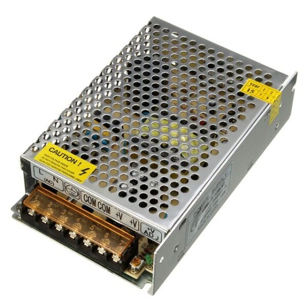
12V 10A SMPS – 120W DC Metal Power Supply
Regulated 12V supply for powering the control circuitry and microcontroller in your TRIAC-based AC power controller projects.
Safety, Isolation, and Practical Tips
TRIAC circuits operate at mains voltage. This section is non-negotiable reading before you build anything.
Mains Safety Rules
- ALWAYS work with the circuit UNPLUGGED from mains while making connections or modifications
- Use an isolation transformer or variac when testing mains-connected circuits on a bench
- Place mains-voltage components inside an insulated enclosure before powering from the wall
- Keep all components rated for at least 400V (use 630V for extra safety margin)
- Use a fuse on the mains input (appropriately rated for your load)
Isolation for Microcontroller Control
If you want to control a TRIAC from an Arduino or microcontroller, you MUST use an optocoupler to isolate the low-voltage control circuit from the mains-voltage TRIAC side. The MOC3041 is an optocoupler with a built-in DIAC-equivalent zero-crossing detector, perfect for microcontroller-driven TRIAC control. The MOC3020/MOC3021 is used when you want phase-angle control from a microcontroller (you manage zero-crossing detection in software).
Heatsinking the TRIAC
TRIACs dissipate power (typically 1-2W at full load due to the ~1.5V on-state voltage drop). For loads above 100W, mount the TRIAC to a heatsink. For BT136 in TO-220 package, a small aluminium heatsink with thermal paste is sufficient for loads up to 500W at ambient temperatures under 40 degC. India summers can push ambient to 45 degC — derate accordingly or use a larger heatsink.
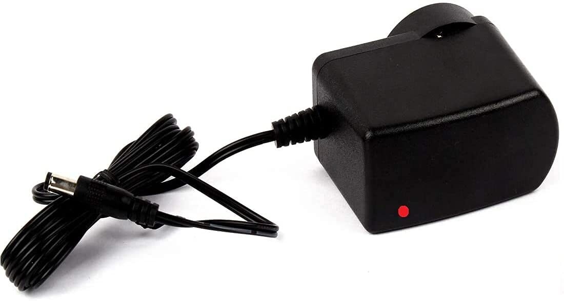
12V 2A Power Supply with 5.5mm DC Plug Adapter
Safe DC power supply for your control circuit development. Use this to power Arduino and isolated control boards while developing TRIAC projects.
Frequently Asked Questions
Q: Can I control an induction motor with a TRIAC dimmer?
With caution. Phase-angle control on inductive loads produces large reactive currents and severe harmonics. A simple TRIAC dimmer designed for resistive loads may overheat or destroy the TRIAC when connected to a motor. Use a TRIAC designed with higher dv/dt rating, a proper snubber, and ensure the motor is rated for variable voltage. Fan regulators in India that control ceiling fans are specifically designed with inductive load snubber values.
Q: What is the difference between a TRIAC and an SSR (Solid State Relay)?
An SSR (Solid State Relay) is a packaged module that contains a TRIAC (or SCR pair) plus an internal optocoupler, zero-crossing circuit, and snubber. It provides the isolation and EMI control built in. For Arduino projects where simplicity and safety matter more than cost, an SSR is safer than a bare TRIAC circuit. For custom circuit design and cost-sensitive volume production, a discrete TRIAC circuit gives more flexibility.
Q: Why does my dimmer cause a buzzing noise in the light or motor?
Phase-angle control creates a chopped waveform rich in harmonics. The magnetic components in transformers and motors vibrate at these harmonic frequencies. Adding a small inductor (a few mH) in series with the load and an RC snubber across the TRIAC reduces harmonics and the associated buzzing. Some loads are simply not compatible with phase-angle control.
Q: Can I use a TRIAC with an LED bulb?
Most LED bulbs are not dimmable with a phase-angle TRIAC dimmer because the LED driver inside the bulb requires a regulated DC supply. Chopping the AC with a TRIAC confuses the driver’s power factor correction circuit. Use only LED bulbs explicitly labelled “dimmable” with TRIAC dimmers, and verify compatibility. Some LED bulb datasheets list compatible dimmer types.
Q: What is the holding current of a TRIAC and why does it matter?
Holding current (IH) is the minimum current a TRIAC needs flowing through MT1-MT2 to stay latched ON after being triggered. If the load current drops below IH (typically 5-100mA depending on the device), the TRIAC turns off even if still in a half-cycle. This matters with very light loads: if your load draws less current than the holding current, the TRIAC may not stay on reliably.
Build your AC power control projects safely. Zbotic.in stocks resistors, capacitors, transistors, and all the passive components you need for your TRIAC circuit builds. Browse components and get them delivered anywhere in India.


Add comment