
The TP4056 charging module wiring is one of the most searched topics among Indian electronics hobbyists — and for good reason. This tiny, inexpensive module is the foundation of countless DIY projects: power banks, Arduino portable builds, IoT sensor nodes, solar lanterns, and more. But wire it incorrectly, and you risk damaging your battery, your circuit, or worse. This guide covers everything from pinout basics to full protection circuit wiring, so you can build safely and confidently.
Table of Contents
- What Is the TP4056 IC?
- Module Variants: With and Without Protection
- TP4056 Module Pinout Explained
- Basic Wiring: Charging Only
- Full Wiring: Charging + Load with DW01A Protection
- Setting the Charging Current (RPROG)
- Safety Considerations
- Common Wiring Mistakes to Avoid
- Project Ideas Using TP4056
- FAQ
What Is the TP4056 IC?
The TP4056 is a complete constant-current/constant-voltage (CC/CV) linear charger IC for single-cell lithium-ion batteries. Manufactured by NanJing Top Power ASIC Corp, it is designed specifically for charging 3.7 V Li-Ion or Li-Polymer cells to a final voltage of 4.2 V.
Key specifications of the TP4056 IC:
- Input voltage: 4 V to 8 V (typical 5 V USB)
- Charge voltage: 4.2 V (±1% accuracy)
- Maximum charge current: 1,000 mA (set by external RPROG resistor)
- Package: SOP-8 (on most breakout modules)
- Thermal regulation: Built-in — reduces current automatically if the die exceeds 120°C
- Charge completion: Automatic — terminates when current drops to 1/10 of the programmed charge current
- LED indicators: CHRG pin (charging) and STDBY pin (charge complete) — driven by the module PCB
The TP4056 does NOT include battery protection (over-discharge, over-current, short-circuit). That is why modules come in two variants — with and without the DW01A protection IC.
Module Variants: With and Without Protection
TP4056 Without Protection
This is the basic module containing only the TP4056 IC. It handles charging only. The output pins (B+ and B-) connect directly to the battery. There is no protection against:
- Over-discharge (draining battery below 2.5 V damages it)
- Over-current from the battery
- Short-circuit on the output
Use case: Applications where the downstream circuit already has its own protection, or you are using a separate BMS. Also used for educational purposes or where load and charging are never simultaneous.
TP4056 With Protection (DW01A + 8205A)
This is the recommended module for most projects. It adds the DW01A protection IC and two 8205A N-channel MOSFETs. The combined circuit provides:
- Over-charge protection: Cuts off charging if cell voltage exceeds ~4.28 V
- Over-discharge protection: Cuts off load if cell voltage drops below ~2.4 V
- Over-current protection: Cuts off if discharge current exceeds ~3 A
- Short-circuit protection: Near-instant cut-off
Use case: The vast majority of DIY projects. Always prefer this variant unless you have a specific reason not to.
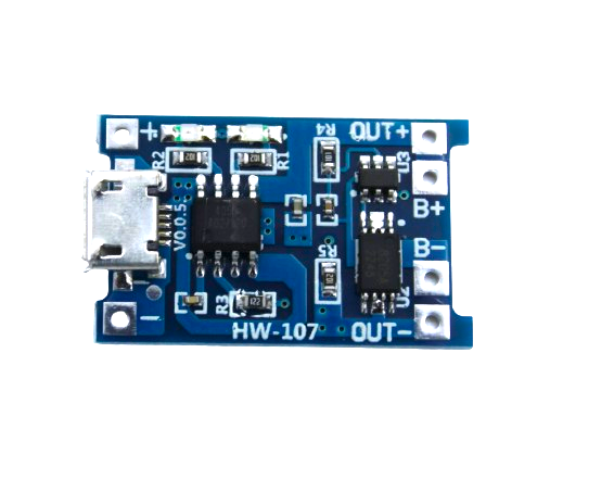
TP4056 1A Li-Ion Battery Charging Board Micro USB with Protection
Complete TP4056 module with DW01A over-charge, over-discharge, and short-circuit protection. Micro USB input, 1A charge rate, red/blue status LEDs. The safest choice for single-cell 3.7V Li-Ion projects.
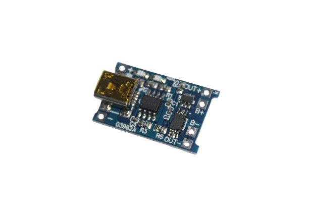
TP4056 1A Li-ion Charging Module with Protection – Mini USB
Mini USB variant of the popular TP4056 protection module. Ideal for retro-style projects or where Micro USB connectors are preferred. Full DW01A protection included.
TP4056 Module Pinout Explained
The standard TP4056 breakout module (with protection) has the following pads:
| Pin Label | Description | Notes |
|---|---|---|
| IN+ / VCC | Positive supply input (5 V from USB) | 4 V to 8 V acceptable |
| IN- / GND | Ground / negative supply input | Common ground |
| B+ / BAT+ | Battery positive terminal | Connect to cell positive |
| B- / BAT- | Battery negative terminal | Connect to cell negative |
| OUT+ (protection modules only) | Protected load output positive | Connect your circuit here, NOT to B+ |
| OUT- (protection modules only) | Protected load output negative | Connect your circuit here, NOT to B- |
Basic Wiring: Charging Only
For a basic no-protection TP4056 module used purely for charging:
- Connect USB 5 V to IN+ and IN- (or use the built-in USB connector)
- Connect B+ to the positive terminal of your 3.7 V Li-Ion cell
- Connect B- to the negative terminal of your 3.7 V Li-Ion cell
- Connect your load circuit to B+ and B- as well
Warning: With no-protection modules, you must NOT discharge the cell below 3.0 V. Set a low-voltage cutoff in your firmware (e.g., using ADC monitoring on an Arduino).
Full Wiring: Charging + Load with DW01A Protection
This is the correct wiring for most DIY projects using the protection module:
- Power input: USB 5 V → IN+ and IN- (or the module’s built-in USB socket)
- Battery connection: Cell positive → B+, Cell negative → B-
- Load connection: Your project circuit → OUT+ and OUT- (NOT B+ and B-)
- Important: OUT+ and OUT- are the protected outputs routed through the DW01A MOSFETs. Using B+ and B- for your load bypasses the protection entirely.
Can you charge and use the load simultaneously? Yes — the TP4056 charges the battery via the B+/B- path, while the DW01A routes battery power to OUT+/OUT-. Both can operate at the same time. However, note that total available current at OUT is the battery’s discharge capacity, not the USB input current.
Setting the Charging Current (RPROG)
Most breakout modules come with a 1.2 kΩ RPROG resistor, setting the charge current to approximately 1,000 mA (1 A). The formula is:
I_CHG = 1000 / RPROG (in kΩ) mA

Examples:
  1.2 kΩ → 1000 mA (1 A)
  2 kΩ   → 500 mA
  4 kΩ   → 250 mA
  10 kΩ  → 100 mA
For smaller batteries (under 500 mAh), always reduce the charge current. Charging a 300 mAh LiPo at 1 A (over 3C!) will cause rapid heating, gas venting, and possible fire. General rule: charge at 0.5C maximum — a 500 mAh cell should be charged at 250 mA max.
To change RPROG on a module: desolder the existing SMD resistor and replace it with the correct value. This requires basic SMD rework skills.
Safety Considerations
- Never charge damaged or swollen batteries with a TP4056. Inspect cells before connecting.
- Do not leave charging unattended in enclosed spaces, especially for large cells. The TP4056 generates heat during charging — mount it with ventilation.
- Use the correct battery chemistry. The TP4056 is calibrated for 4.2 V Li-Ion/LiPo. It will overcharge LiFePO4 cells (which charge to only 3.65 V).
- Input polarity matters. Reversing the IN+/IN- will likely destroy the module immediately.
- Battery polarity matters. Reversing B+/B- will also destroy the module.
- Heatsinking: At full 1 A charge on a 5 V supply, the TP4056 dissipates up to 800 mW as heat. On a bare module, this is manageable, but embedding it in a sealed enclosure risks thermal shutdown and reduced charge efficiency.
Common Wiring Mistakes to Avoid
Mistake 1: Connecting Load to B+ Instead of OUT+
The most common mistake. If you connect your Arduino or project circuit to B+ and B-, you bypass the protection circuit entirely. Any over-current event will not be caught by the DW01A.
Mistake 2: Using TP4056 for LiFePO4 Cells
LiFePO4 has a different charge curve — nominal 3.2 V, full charge 3.65 V. The TP4056 terminates at 4.2 V and will over-charge LiFePO4, degrading it rapidly. Use a dedicated LiFePO4 charger IC.
Mistake 3: Charging While Drawing Heavy Load
While simultaneous charge + use is technically possible, drawing 1 A from OUT+ while charging at 1 A via USB creates a 2 A demand the battery may not sustain well. Keep total current flow balanced.
Mistake 4: Assuming Protection Module Protects Against All Shorts
The DW01A protection reacts within microseconds, but a hard short on OUT+ can still cause a brief current spike. Never short the output deliberately to “test” the protection.
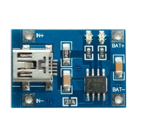
TP4056 1A Li-ion Battery Charging Module – Mini USB
Compact TP4056 charging-only module with Mini USB connector. Perfect for embedded projects where you need a simple, light charger solution without onboard protection (pair with external BMS).
Project Ideas Using TP4056
1. Solar-Powered Arduino Weather Station
A 5 V solar panel charges a 2,000–3,000 mAh 18650 cell via the TP4056. An Arduino Nano running on the protected output reads temperature/humidity (DHT22) and transmits via ESP8266. The TP4056’s thermal regulation handles cloudy-day voltage fluctuations from the panel gracefully.
2. Portable Bluetooth Speaker
A TP4056 module combined with a 2,000 mAh Li-Ion cell and a PAM8403 amplifier creates a palm-sized Bluetooth speaker. Charge via USB Micro, play via Bluetooth. Total BOM under ₹300.
3. Wearable LED Badge
A 500 mAh LiPo (with RPROG changed to 4 kΩ for 250 mA charge) powers a WS2812B LED matrix controlled by an ATtiny85. The TP4056 charges from any USB power bank when worn at events.
4. IoT Soil Moisture Sensor (Field Deployed)
A small solar panel + TP4056 + 18650 cell + ESP32 deep sleep loop reads soil moisture and uploads to ThingSpeak every 15 minutes. The TP4056 keeps the cell topped up from daytime solar.
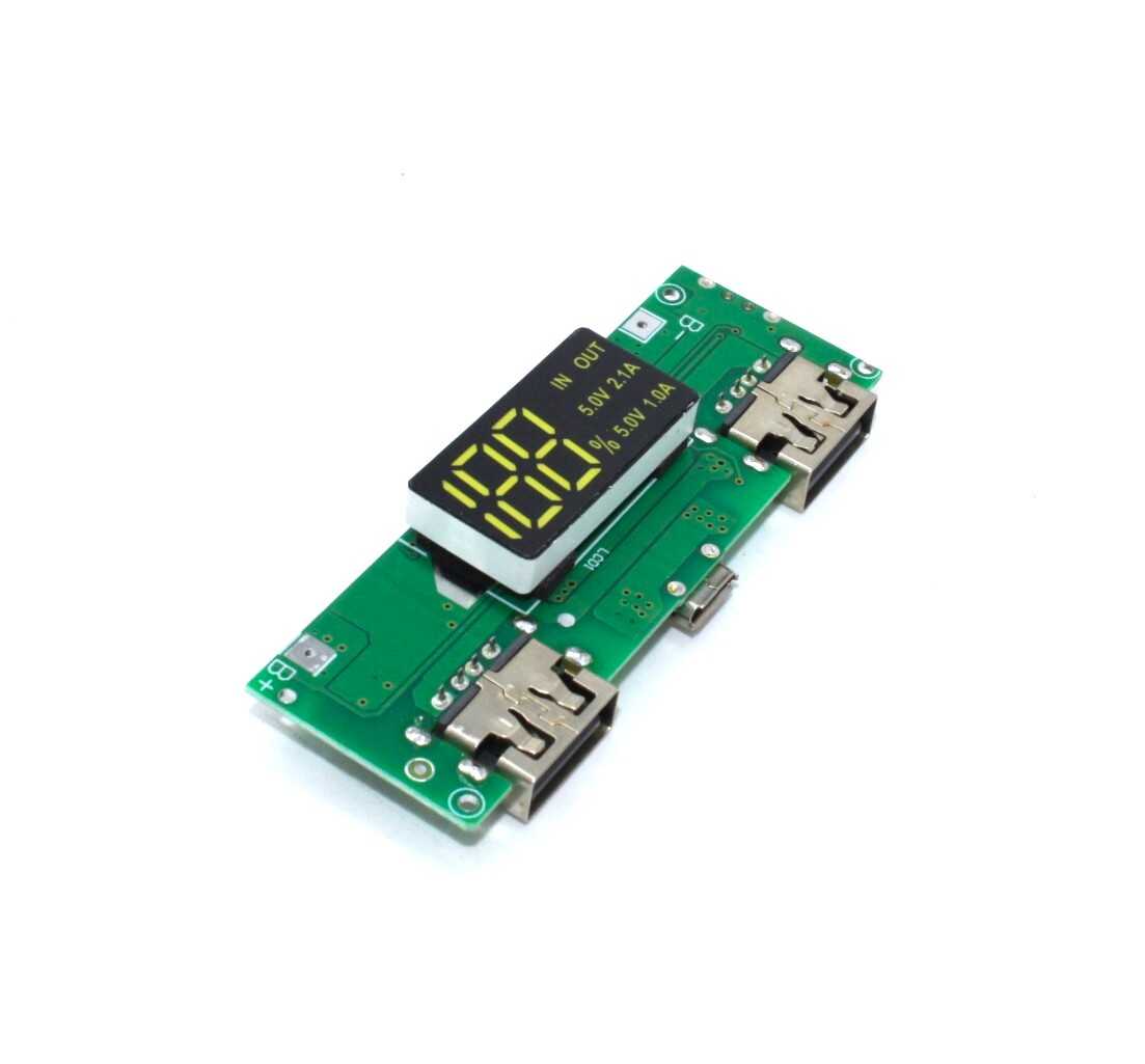
18650 5V 1A/2A Lithium Battery Digital Display Charging Module
A step up from the basic TP4056 — this module includes an integrated boost converter for 5 V USB output, digital charge indicator, and dual USB ports. Perfect for power bank projects using a single 18650 cell.
Frequently Asked Questions
Can TP4056 charge two batteries simultaneously?
No. The TP4056 is designed for single-cell (1S) 3.7 V Li-Ion charging only. For multi-cell packs, you need a dedicated multi-cell charger or multiple individual TP4056 modules — one per cell.
Why is my TP4056 getting very hot during charging?
The TP4056 is a linear regulator — all excess voltage is dissipated as heat. At 5 V input charging at 1 A with a 3.7 V cell: (5 – 3.7) × 1 A = 1.3 W dissipated. This is normal and causes the IC to get warm. The built-in thermal regulation reduces charge current automatically if temperature is too high. Ensure the module is not in a sealed space.
The red LED is blinking — what does it mean?
A blinking CHRG LED typically indicates the protection circuit has tripped due to battery over-discharge (cell voltage below ~2.4 V). To recover: apply a brief 5 V input to allow the DW01A to reset, then proceed with normal charging. If it continues blinking, the cell may be damaged.
Can I use a 9V adapter with TP4056?
Technically the IC accepts up to 8 V. A 9 V adapter may damage it. At 9 V input charging at 1 A: (9 – 3.7) × 1 A = 5.3 W dissipation — far too much for the tiny IC. Always use 5 V USB for powering the TP4056.
What is the difference between TP4056 and IP5306?
The TP4056 is a bare charging IC with optional protection via external DW01A. The IP5306 is an integrated power bank IC with built-in boost converter (5 V output), dual USB, LED indicators, and protection — all in one chip. For a fully featured power bank, IP5306 is simpler. For embedded charging in custom projects, TP4056 gives more flexibility.
Build Your Battery Project Today
Zbotic stocks TP4056 modules (Micro USB and Mini USB variants), 18650 holders, BMS boards, and boost converters. Get everything for your DIY battery project in one order with fast shipping across India.


Add comment