
If you’ve ever wanted to build a Stewart Platform 6-DOF parallel robot with servos, you’re stepping into one of the most fascinating areas of robotics engineering. The Stewart Platform — also called a hexapod — is a six-degree-of-freedom parallel manipulator capable of motion in all three translational and three rotational axes. From flight simulators to precision surgical tools, its real-world applications are enormous. In this guide, we walk through the complete build process: kinematics, platform geometry, servo selection, wiring, Arduino code, and calibration.
What Is a Stewart Platform?
Invented by V. E. Gough in 1954 and later popularized by D. Stewart in 1965, the Stewart Platform is a type of parallel robot where the end-effector (top plate) is connected to the base (bottom plate) via six independent linear or rotary actuators. Unlike serial robots (such as a standard robot arm), all six actuators share the load simultaneously, giving the platform exceptional stiffness, precision, and load-bearing capacity for its size.
In hobby and educational builds, the six actuators are typically SG90 or MG996R servo motors. Each servo drives a pushrod (connecting rod) that attaches to the top platform via a ball joint or universal joint. By precisely commanding the angle of each servo, you can tilt, roll, pitch, yaw, heave, and surge the top plate in real time.
Common applications include:
- Flight and driving simulators
- Camera stabilization gimbals
- Earthquake simulation tables
- CNC machining heads
- Medical rehabilitation equipment
- Educational robotics demonstrations
6 Degrees of Freedom Explained
DOF stands for Degrees of Freedom — the number of independent parameters that define the position and orientation of a rigid body in space. A Stewart Platform achieves all 6:
- Surge (X): Forward and backward translation
- Sway (Y): Left and right translation
- Heave (Z): Up and down translation
- Roll (Rx): Rotation about the X axis
- Pitch (Ry): Rotation about the Y axis
- Yaw (Rz): Rotation about the Z axis
Because six servos independently control six rods, every combination of these six movements is achievable within the mechanical limits of the platform. This is the core advantage over gimbals (typically 3-DOF) or pan-tilt systems (2-DOF).
Choosing the Right Servos
Servo selection is critical. Each servo must be strong enough to support the weight of the top platform plus any payload, while being fast enough for smooth, real-time motion. Here are key parameters to evaluate:
- Torque: For a lightweight acrylic or 3D-printed platform (<500g payload), SG90 (1.8 kg·cm) or MG90S (2.2 kg·cm) servos are sufficient. For heavier payloads, upgrade to MG996R (9.4 kg·cm) or digital servos like DS3218.
- Speed: Aim for at least 0.12 sec/60° for fluid animation. Slower servos introduce lag that makes the platform feel sluggish.
- Resolution: Analog servos have ~500 position steps over 180°. Digital servos offer finer resolution and hold position better under load.
- Center detent: Avoid cheap servos with large deadbands — they cause jitter at the neutral position.
You will also need servo horns (single-arm or circular), M2 or M3 pushrods (threaded rods with ball joints or clevises), and a way to mount the servos on the base plate at the correct angular offsets (typically 60° apart).
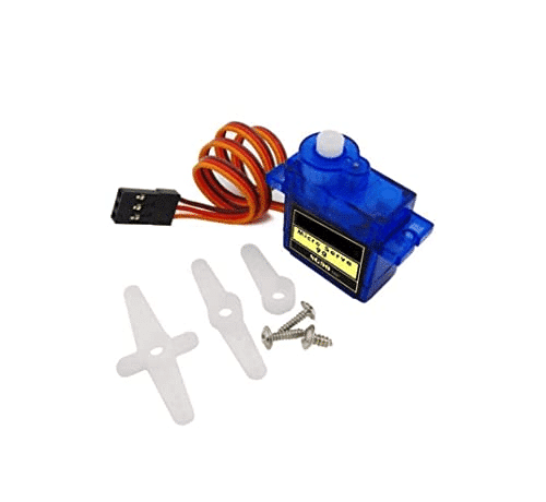
TowerPro SG90 180 Degree Rotation Servo Motor
The classic SG90 servo — lightweight (9g), 1.8 kg·cm torque, 180° range. Ideal for small Stewart Platforms with light payloads. Requires only 5V and standard PWM.
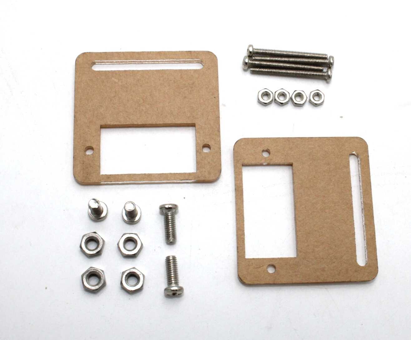
Servo Mount Holder Bracket For SG90/MG90 (Pack of 2)
Sturdy metal servo brackets for mounting SG90/MG90 servos at precise angles on your Stewart Platform base. Included mounting hardware simplifies alignment.
Platform Geometry and Materials
The geometry of the Stewart Platform determines its range of motion and mechanical stiffness. The key parameters are:
- Base radius (Rb): The circumscribed radius of the base plate servo attachment points
- Platform radius (Rp): The circumscribed radius of the top plate attachment points
- Rod length (L): The length of the pushrods connecting servos to the top plate
- Servo arm length (a): The length of the servo horn
- Angular offset (β): The angle between paired servo attachment points (typically 20–40°)
For a beginner build, use these approximate values:
- Base radius: 80–100 mm
- Platform radius: 50–70 mm
- Rod length: 120–160 mm
- Servo arm: 25–35 mm
Materials: 3D-printed PLA or PETG plates are ideal for prototyping — laser-cut acrylic (3mm) also works well. The pushrods can be M3 threaded rods cut to length, with M3 ball-link ends or Dupont pin headers as universal joints for a budget build. Proper ball joints (from RC car suppliers) give smoother motion and longer life.
Inverse Kinematics for the Stewart Platform
Inverse kinematics (IK) is the math that translates a desired position and orientation of the top plate into the six servo angles required. This is where most builders get stuck, but it is manageable with the right approach.
The algorithm steps for each of the six legs:
- Define the desired position vector P = (x, y, z) and rotation R = (roll, pitch, yaw) of the top plate.
- Apply the rotation matrix R to each top-plate attachment point Pi to get its world-space position.
- Compute the leg vector: Li = Pi + P – Bi, where Bi is the base attachment point.
- From leg length and servo arm length, calculate the servo angle using the trigonometric formula:
sin(α) = (L² - (l² - a²)) / (2·a·√(lx² + lz²)) - Map the servo angle to microseconds for PWM output.
Several open-source Arduino libraries (such as Stewart.h from GitHub) implement this for you. You pass (x, y, z, roll, pitch, yaw) and the library returns six servo positions. For beginners, start with a pre-written IK sketch from platforms like GitHub and modify it for your geometry.
Arduino Wiring and Control Code
For a 6-servo Stewart Platform, you need a microcontroller with at least six PWM output pins. Options:
- Arduino Mega 2560: 15 PWM pins — most commonly used for Stewart platforms. Powers the servo library easily.
- Arduino Uno + PCA9685 16-channel PWM driver: Offloads PWM generation to the dedicated I²C chip, freeing up the MCU for IK math.
- ESP32: 16 ledc channels, Wi-Fi/Bluetooth for remote control — great for advanced builds.
Wiring:
- Servo signal wires → Arduino digital pins 3, 5, 6, 9, 10, 11 (PWM)
- Servo power (VCC) → Dedicated 5V 3A power supply (never use the Arduino 5V rail for 6 servos)
- All grounds connected (Arduino GND + power supply GND)
Basic Arduino sketch structure:
#include <Servo.h>
Servo s[6];
void setup() {
  for(int i=0; i<6; i++) s[i].attach(3+i);
  // Set all servos to neutral (90°)
  for(int i=0; i<6; i++) s[i].write(90);
}
void loop() {
  // Call IK function, update servo positions
  updatePlatform(x, y, z, roll, pitch, yaw);
  delay(20); // 50 Hz update rate
}
Always power your servos from a dedicated bench power supply or a 2S LiPo with a BEC — six SG90 servos can draw up to 3A peak under load, which will reset or damage an Arduino if drawn from its 5V pin.
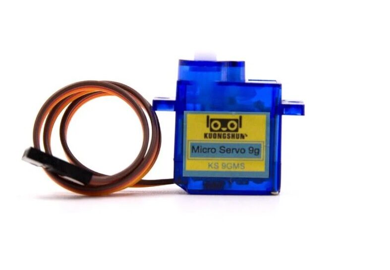
Servo SG90 9g 180 Degree
Budget-friendly SG90 servo for multi-servo projects. Consistent 1.8 kg·cm torque at 5V. Perfect for building a 6-servo Stewart Platform at minimal cost.
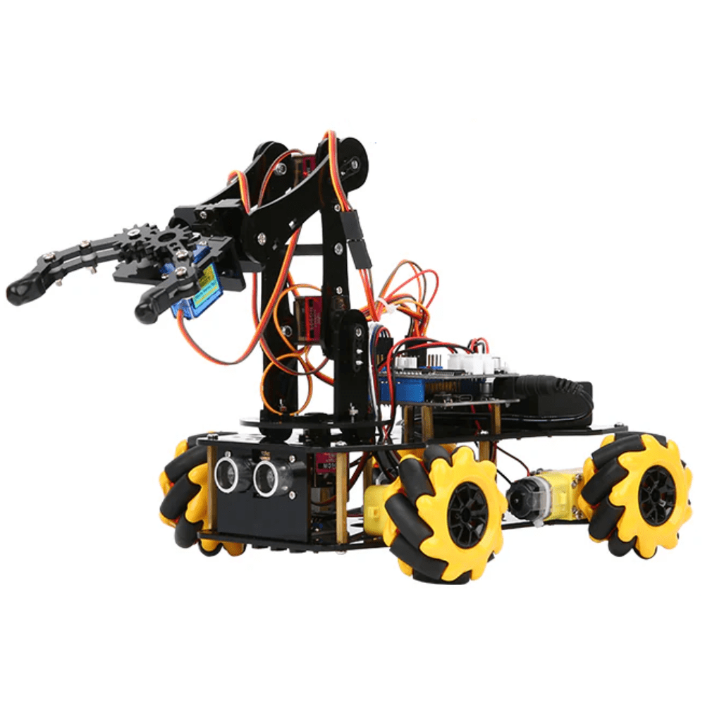
ACEBOTT ESP32 5-DOF Robot Arm Kit Expansion Pack
Great companion kit to understand multi-servo control and IK concepts. ESP32-based with graphical programming support — excellent for learning servo coordination before tackling a Stewart Platform.
Calibration and Testing
Calibration is what separates a working Stewart Platform from a twitching mess. Follow this process:
- Neutral calibration: With all IK inputs at zero (flat, centered position), verify that the top plate is perfectly level using a spirit level. Adjust servo horn attachment positions until level is achieved.
- Servo trim: Use
servo.writeMicroseconds()instead ofservo.write()for finer control. Center is typically 1500 µs; adjust per servo to achieve level. - Range test: Command maximum roll, pitch, and heave to verify the rods don’t bind or the servos don’t stall. Reduce range in IK code if binding occurs.
- Speed test: Ramp the platform through a smooth sinusoidal trajectory and watch for overshooting or servo groaning (sign of overloading).
- Load test: Add your payload (camera, sensor array, etc.) and re-verify level and range.
Document each servo’s trim offset in your code as constants — these values are specific to your physical build and will be needed again after reassembly.
Frequently Asked Questions
How many servos does a Stewart Platform need?
A classic Stewart Platform uses exactly 6 servos — one per leg. Each servo controls the length or angle of one leg independently.
What torque servos do I need for a Stewart Platform?
For a lightweight hobby build (acrylic or 3D-printed, no payload), SG90 at 1.8 kg·cm is sufficient. For payloads up to 1 kg, use MG996R at 9.4 kg·cm or a digital servo equivalent.
Can I use stepper motors instead of servos?
Yes, but stepper motors are heavier and require more complex driver circuitry. Servos are standard for hobby Stewart Platforms due to their compact size, built-in feedback, and easy PWM control.
What software controls a Stewart Platform?
Most hobby builds use Arduino with custom IK math or the open-source Stewart.h library. Advanced builds use ROS (Robot Operating System) with a dedicated inverse kinematics node.
Is the Stewart Platform hard to build for beginners?
It is intermediate level. You need basic Arduino programming, understanding of servo control, and patience for mechanical assembly and calibration. Starting with a 5-DOF robot arm kit helps build servo coordination skills first.
Ready to Build Your Stewart Platform?
The Stewart Platform 6-DOF parallel robot is one of the most rewarding builds in hobby robotics. Once calibrated, its smooth, precise motion across all six axes will impress at any science fair, robotics competition, or laboratory demonstration. The key is careful geometry, proper servo power, solid IK math, and patient calibration.
Zbotic stocks all the servos, brackets, and microcontroller kits you need. Start with a pair of SG90 servos and a servo bracket set, confirm your geometry, then scale up to a full six-servo build. Happy building!


Add comment