
Simple FM Transmitter Circuit Using BC547 Transistor
Building a working FM transmitter circuit with BC547 transistor is one of the most exciting entry-level RF projects you can attempt. Imagine broadcasting your phone’s audio to any nearby FM radio — all from a circuit you built yourself using basic components costing under ₹50. The BC547, a ubiquitous NPN transistor available in every Indian electronics store, can be coaxed into oscillating at FM frequencies (88–108 MHz) with the right LC tank circuit. This guide covers the complete theory, schematic, component list, and step-by-step assembly instructions so you can have a working transmitter on the air today.
How FM Transmission Works
FM stands for Frequency Modulation. Unlike AM (Amplitude Modulation), which encodes audio by varying the signal’s amplitude, FM encodes information by varying the carrier signal’s frequency slightly above and below a centre frequency. The deviation in frequency is proportional to the audio signal’s amplitude.
In a simple transistor-based FM transmitter, the audio signal from your microphone or audio source is fed into the base of the oscillator transistor. This audio signal modulates the transistor’s transconductance, which in turn slightly alters the tank circuit’s resonant frequency — producing FM modulation. The RF signal is radiated from a short antenna (typically a 75cm wire cut to quarter-wavelength at 100 MHz).
FM broadcast frequencies in India range from 88.0 MHz to 108.0 MHz, as allocated by the Ministry of Information & Broadcasting. Your homebrew transmitter will operate somewhere in this band depending on the LC tank coil you wind.
BC547 Transistor Basics
The BC547 is a general-purpose NPN bipolar junction transistor in the TO-92 plastic package. While it’s primarily used as a low-frequency amplifier and switch, its transition frequency (fT) of approximately 300 MHz makes it capable of oscillating well into the FM band when used in a Colpitts or Hartley oscillator configuration.
Key BC547 Specifications:
- Type: NPN Silicon BJT
- Package: TO-92 (flat face: Collector–Base–Emitter left to right)
- VCEO (Collector-Emitter voltage): 45V
- VCBO (Collector-Base voltage): 50V
- IC (Collector current): 100mA max
- hFE (DC current gain): 110–800 (BC547C grade)
- fT (Transition frequency): ~300 MHz
- Operating temperature: -65°C to +150°C
In the FM transmitter circuit, the BC547 is biased in its active region and configured as a Colpitts oscillator. The high fT ensures the transistor can amplify at 88–108 MHz with useful gain. The BC548 and BC549 are pin-compatible alternatives with similar performance.
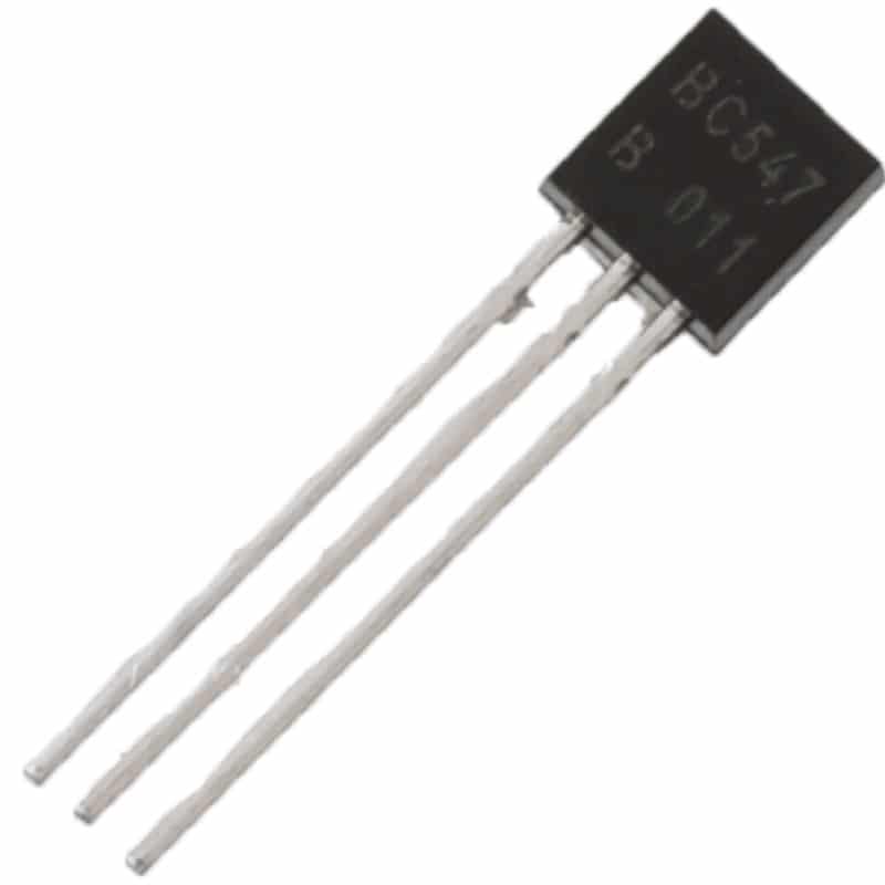
BC547 NPN 100mA Transistor TO-92 (Pack of 10)
The star component of this project. Genuine BC547 transistors in TO-92 package — pack of 10 so you have spares for experimentation.
FM Transmitter Circuit Design
The simplest and most reliable single-transistor FM transmitter uses a Colpitts oscillator topology. Here’s how the circuit works:
Oscillator Stage:
The LC tank circuit consists of a hand-wound air-core coil (L1) and a trimmer capacitor (C1, 10–60pF). Two capacitors in the Colpitts feedback network (C2 and C3, typically 10pF each) form the capacitive voltage divider that feeds oscillation back to the transistor’s emitter. The transistor Q1 (BC547) provides the gain to sustain oscillation.
Bias Network:
R1 (10kΩ) and R2 (1kΩ) form a voltage divider to bias the BC547 base at approximately 1.2V above ground, placing the transistor in active region. R3 (100Ω) is the emitter resistor providing DC stability. The collector is connected to VCC (+9V) through the choke RFC (a 10-turn coil wound on a resistor body, or a commercial RF choke).
Audio Input (Modulation):
The audio signal from your smartphone headphone jack, electret microphone, or audio source is coupled into the BC547’s base through a 100nF capacitor (C4). The audio signal modulates the transistor’s base voltage, causing small variations in the tank circuit’s oscillation frequency — this is the FM modulation. A 22kΩ resistor (R4) isolates the audio source from the RF circuit and sets the audio input impedance.
Antenna:
A 75cm bare copper wire connected to the collector through a small capacitor (4.7pF) serves as the quarter-wavelength antenna at approximately 100 MHz. Keep the antenna wire straight and vertical for best omnidirectional radiation.
Complete Circuit Connections:
- Q1 BC547: Base → R1 voltage divider junction + audio input via C4
- Q1 Emitter → R3 (100Ω) → GND; also connects to C2–C3 capacitive divider
- Q1 Collector → RFC (choke) → VCC; also connects to L1-C1 tank, C2 feedback, and antenna via 4.7pF cap
- L1 coil: 5–6 turns of 24 AWG copper wire, 5mm diameter air core, one end to collector, other end to GND through C3 (10pF)
- C1 (20pF trimmer): across the coil L1 for frequency adjustment
Complete Component List
| Ref | Component | Value |
|---|---|---|
| Q1 | NPN Transistor | BC547 |
| L1 | Air core coil | 5–6 turns, 24AWG, 5mm dia |
| C1 | Trimmer capacitor | 10–60pF |
| C2, C3 | Ceramic capacitor | 10pF each |
| C4 | Coupling capacitor | 100nF (0.1µF) |
| C5 | Antenna coupling cap | 4.7pF |
| C6 | Supply decoupling | 100nF + 100µF in parallel |
| R1 | Carbon film resistor | 10kΩ |
| R2 | Carbon film resistor | 1kΩ |
| R3 | Carbon film resistor | 100Ω |
| R4 | Carbon film resistor | 22kΩ |
| RFC | RF choke | 1µH (or 10-turn on resistor) |
| Power | 9V battery or regulated supply | 9V DC |
| ANT | Copper wire antenna | 75cm bare wire |
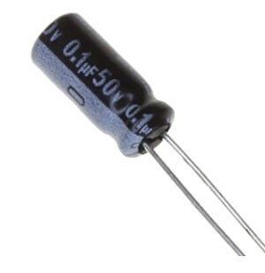
0.1µF 50V Capacitor (Pack of 50)
Used as the audio coupling and decoupling capacitor in the FM transmitter. Pack of 50 gives you plenty for multiple builds and experiments.
Assembly and Wiring Guide
RF circuits are sensitive to layout. Poor layout is the number one reason homebrew FM transmitters fail to oscillate or have poor range. Follow these guidelines:
Coil Winding (L1):
Wind 5–6 turns of 24 AWG enamelled copper wire around a 5mm diameter former (a ballpoint pen cap works perfectly). Leave the turns slightly spaced — about half a wire diameter apart. After winding, remove the former, and you have an air-core inductor. This gives approximately 60–80nH inductance, which resonates with a 10–40pF capacitor in the FM band. You can stretch or compress the coil slightly to fine-tune frequency.
Layout Tips:
- Keep the tank circuit (L1, C1, C2, C3) physically close together and away from the power supply decoupling.
- Use short lead lengths — trim all component leads to minimum length on the PCB or stripboard.
- Keep the audio input wires away from the RF tank to avoid audio feedback.
- The RFC (RF choke on the collector) is critical — without it, the RF energy will be shunted to the power supply and your transmitter won’t radiate.
- Use a small 100pF capacitor from VCC to GND right at the transistor collector as an additional RF bypass.
Powering the Circuit:
A 9V PP3 battery is the ideal power source for prototyping — it’s isolated from the mains, portable, and provides a clean supply. If using a wall adapter, add an extra 100µF electrolytic + 100nF ceramic in parallel across the supply rails on the PCB to reduce any PSU ripple from appearing as low-frequency modulation (hum).

10CM Female To Female Breadboard Jumper Wires 2.54MM – 40Pcs
Handy for connecting your audio source to the FM transmitter breadboard circuit. Short 10cm wires minimize RF pickup on signal lines.
Frequency Tuning and Range
Once your circuit is assembled and powered, the next step is tuning it to a free frequency in the FM band and checking its range.
Finding a free frequency:
Tune your FM radio across the 88–108 MHz band and note which frequencies in your area are unused or have weak signals. In most Indian cities, frequencies between 88–90 MHz or above 106 MHz are often clear. Pick a target frequency.
Tuning the transmitter:
Use a small non-metallic trimmer (plastic screwdriver) to adjust the trimmer capacitor C1. As you increase capacitance, the resonant frequency decreases; decreasing capacitance increases frequency. Bring your FM radio tuned to your target frequency close to the transmitter and adjust C1 until you hear audio. You can also gently squeeze or expand the L1 coil turns to make coarse adjustments.
Expected range:
With 9V supply, a single BC547, and a 75cm wire antenna, expect a range of approximately 5–30 metres in open space (less through walls). This is sufficient for personal use within your home or workshop. Range can be improved by increasing supply voltage (up to 12V), adding a second amplifier transistor stage, or using a properly matched antenna.
Improving audio quality:
If the audio sounds distorted or has hum, first replace the 9V battery (low battery = more distortion). Add a 100µF filter capacitor across the supply rails. Reduce the audio input level — FM transmitters can be easily overdriven, causing excessive frequency deviation and distortion. A 10kΩ potentiometer in series with the audio input can serve as a modulation depth control.
Legal Note for India
In India, the operation of FM transmitters is regulated by the Wireless Planning and Coordination (WPC) Wing under the Ministry of Communications. Operating a transmitter without a valid licence is illegal under the Indian Wireless Telegraphy Act, 1933, and the Indian Telegraph Act, 1885. However, extremely low-power transmitters (under 50 microwatts ERP) are generally considered de minimis for personal use in the home. The circuit described in this article produces milliwatt-level power — well within safe experimental range at short distances. Never transmit on licensed commercial FM stations’ frequencies, and do not use the transmitter in a way that causes interference to licensed services. This project is intended purely for educational and experimental purposes within your own premises.

0 Ohm 0.25W Carbon Film Resistor (Pack of 100)
Stock up on carbon film resistors for your FM transmitter and other electronics projects. These 0.25W resistors cover all the bias and coupling resistor values needed.
Frequently Asked Questions
Q1: Why isn’t my FM transmitter oscillating?
Most common causes: (1) The BC547 is inserted backwards — double-check pin orientation (flat side of TO-92 facing you: E–B–C from left to right in many datasheets, but verify yours). (2) The coil has too many or too few turns — try 4, 5, or 6 turns to find the sweet spot. (3) The trimmer capacitor is fully open or shorted. (4) Missing or incorrect RFC — the collector choke is critical. (5) Supply voltage too low — use a fresh 9V battery.
Q2: Can I use a 2N2222 or BC548 instead of BC547?
Yes. The 2N2222 (TO-18 or TO-92 package) and BC548 are both NPN transistors with similar fT and can be used as drop-in replacements in this FM transmitter circuit with no component value changes. The BC548 has a lower VCEO (30V vs 45V for BC547) which doesn’t matter at 9V supply.
Q3: How do I extend the transmitter range?
To increase range: (a) Increase supply voltage to 12V (stay within BC547 ratings). (b) Add a second RF amplifier stage (e.g., another BC547 in common-emitter configuration) after the oscillator. (c) Use a properly tuned antenna — a quarter-wave vertical (75cm) with a ground plane improves radiation efficiency significantly. (d) Use a higher-gain transistor like the BF199 or BF494 designed for RF operation.
Q4: Can I use a microphone instead of a line-level audio source?
Yes — use an electret condenser microphone (ECM) capsule. An ECM needs a bias voltage (typically 1–3V through a 4.7kΩ resistor from VCC). Connect the ECM output through a 100nF coupling cap to a simple single-transistor audio preamplifier (common emitter, BC547, gain ~40), then feed the preamplifier output through another 100nF cap into the FM transmitter’s audio input. This creates a complete wireless microphone system.
Q5: My transmission has lots of hum — how do I fix it?
Hum (50 Hz or 100 Hz interference) is almost always from the power supply. Add a larger filter capacitor (470µF or 1000µF) across the supply rails, and ensure your wall adapter output is regulated. A linear regulator (7809 for 9V) upstream of the FM transmitter circuit provides much cleaner DC than most unregulated wall adapters. Alternatively, use a 9V battery — it’s inherently hum-free.
Get Your BC547 and Components at Zbotic
All the components for this FM transmitter project — BC547 transistors, capacitors, resistors, jumper wires, and prototype boards — are available at Zbotic. Fast shipping across India with delivery to 19,000+ pin codes.


Add comment