
Litz Wire vs Solid Copper: High Frequency Winding Guide for Makers
If you have ever wound a transformer, inductor, or resonant coil, you have faced the fundamental question: should you use litz wire vs solid copper? The answer is not always obvious. At low frequencies, solid copper wins hands-down for its simplicity and low DC resistance. But as frequency climbs into the tens of kilohertz range and beyond, solid wire suffers from skin effect and proximity effect — two phenomena that can dramatically increase your conductor losses and tank your circuit efficiency. This guide explains both wire types in depth and helps Indian makers and electronics students choose the right conductor for every application.
Understanding Solid Copper Wire
Solid copper wire — also called solid-core wire — is a single, monolithic conductor made from a single strand of copper. It is the simplest, most economical form of copper conductor. In India, it is available from sub-millimetre enamelled wire all the way up to large gauge cables for power distribution.
The key properties of solid copper that make it attractive:
- Low DC resistance: The full cross-sectional area carries current, giving minimum DC resistance per unit length.
- Easy to solder: Single strand means no strands to fray. Enamelled versions can be tinned directly.
- Compact winding: Solid wire packs tightly onto bobbins, maximising copper fill factor in transformers.
- Inexpensive: No special construction needed. Widely available across India from electrical shops and online stores.
However, solid wire has a fundamental limitation at high frequencies: the skin effect. Understanding this is key to deciding between litz and solid conductors.

0.1MM Copper Enamelled Repair Reel Wire
Ultra-fine 0.1mm enamelled copper wire — excellent for fine winding work on small inductors, transformers, and sensor coils at moderate frequencies.
The Skin Effect Explained
The skin effect is a phenomenon where alternating current (AC) at higher frequencies tends to flow near the surface — or “skin” — of a conductor, rather than uniformly through its entire cross-section. This happens because the changing magnetic field induced by the current creates eddy currents inside the conductor that oppose current flow in the core of the wire.
The key parameter is the skin depth (δ), which describes how deeply current penetrates into the conductor:
δ = √(ρ / (π × f × μ))
Where ρ is resistivity (1.72 × 10⁻⁸ Ω·m for copper), f is frequency in Hz, and μ is permeability. For copper specifically:
δ (mm) ≈ 66.2 / √f (Hz)
| Frequency | Skin Depth in Copper | Impact on 1mm Wire |
|---|---|---|
| 50 Hz (mains) | 9.38 mm | Negligible — full cross-section carries current |
| 1 kHz | 2.1 mm | Slight — most wires unaffected |
| 10 kHz | 0.66 mm | Moderate — 1mm wire loses ~25% effective area |
| 100 kHz | 0.21 mm | Severe — most inner copper wasted |
| 1 MHz | 0.066 mm | Extreme — only thin surface layer carries current |
When operating at 100 kHz (common in SMPS transformers, LLC converters, and wireless charging coils), a 1 mm solid copper wire effectively has only its outermost 0.21 mm shell carrying current. The interior copper becomes dead weight — contributing resistance but no current-carrying capacity.
Proximity Effect in Windings
The proximity effect is the skin effect’s less-discussed cousin, but often more damaging in multi-layer coil windings. It occurs when the magnetic field from one conductor induces eddy currents in neighbouring conductors, further distorting current distribution.
In a tightly wound multilayer inductor or transformer winding, each conductor influences all its neighbours. The proximity effect can increase AC resistance by a factor of 5–20× compared to the already-poor high-frequency DC resistance of the wire. This is why SMPS transformers using solid copper wire run hot and lose efficiency at high switching frequencies — it is not just the core, it is the winding losses too.
The proximity effect increases with:
- More winding layers (exponentially worse per layer)
- Tighter conductor packing
- Higher operating frequency
- Larger conductor diameter relative to skin depth
What Is Litz Wire and How Does It Work?
Litz wire (from the German Litzendraht, meaning “woven wire”) is a conductor made from many individually insulated thin strands that are braided or twisted together in a specific pattern. The key word is individually insulated — each fine strand has its own enamel coating before being twisted into the bundle.
The magic of litz wire lies in its geometry. Because each strand is insulated and twisted through the bundle’s cross-section, every strand periodically occupies the outer and inner positions of the cable. Over the cable’s length, each strand carries equal current — eliminating the current-crowding of the skin effect. The result: the effective AC resistance of litz wire approaches its DC resistance even at high frequencies, as long as the individual strand diameter is smaller than twice the skin depth.
Key litz wire parameters:
- Number of strands: More strands = better high-frequency performance but more complex termination
- Strand diameter: Must be ≤ 2× skin depth at target frequency for effective operation
- Twist pitch: The length of one complete twist cycle — tighter pitch reduces proximity effect
- Insulation: Each strand has enamel (polyurethane or polyesterimide); outer braid may have additional insulation
Practical strand sizing rule for litz wire: For a target frequency f, choose strand diameter d_strand ≤ 2δ = 132/√f mm. For 100 kHz, this gives d_strand ≤ 0.42 mm. A common choice would be 50 strands of AWG 36 (0.12 mm each), which gives adequate current capacity with excellent high-frequency performance.
Litz Wire vs Solid Copper: Head-to-Head Comparison
| Property | Solid Copper | Litz Wire |
|---|---|---|
| DC Resistance | Lower (better) | Slightly higher (extra insulation reduces fill factor) |
| AC Resistance at 100kHz | 5–20× DC resistance | ≈ 1.1–1.3× DC resistance |
| Cost | Low | High (5–20× solid wire) |
| Termination | Easy — strip and solder | Complex — all strands must be stripped individually |
| Winding Fill Factor | High (solid packs tightly) | Lower (gaps between strands + insulation) |
| Flexibility | Rigid (can break with flexing) | Highly flexible |
| Best Frequency Range | < 10 kHz | 10 kHz – 10 MHz |
| Availability in India | Excellent — everywhere | Limited — import or specialty suppliers |
Choosing by Frequency: Practical Crossover Points
Here is a practical guide for Indian makers to decide which wire type to use based on operating frequency:
Below 1 kHz: Always Use Solid Copper
Mains transformers (50 Hz), audio output transformers, power supply filter inductors — all operate at frequencies where skin depth exceeds the wire radius. Solid copper is the clear winner for its lower cost and better fill factor.
1 kHz – 10 kHz: Solid or Fine Stranded
In this range, skin effect begins to matter for wires thicker than about 1 mm. Multi-layer windings should use thin solid wire (below 0.5 mm diameter) or use parallel strands. Litz wire is usually not cost-justified here.
10 kHz – 1 MHz: Prime Litz Wire Territory
This is where SMPS switching transformers (20–500 kHz), LLC resonant converters, wireless charging coils (100–200 kHz), and induction heating coils operate. Litz wire dramatically reduces winding losses and heat. The efficiency gain easily justifies the higher wire cost in power applications.
Above 1 MHz: Neither Works Well — Use PCB Traces
At RF frequencies above 1 MHz, even litz wire becomes lossy because achieving adequately thin strands becomes impractical. PCB traces, coaxial structures, or strip-line conductors are more appropriate at these frequencies.
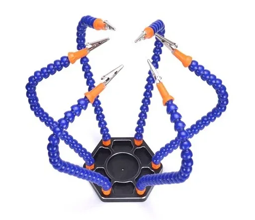
6 Flexible Arms Soldering Station With Swiveling Alligator Clip
A must-have for winding and soldering litz wire — hold coils, cores, and leads in place while you carefully solder each strand for reliable connections.
Practical Winding Tips for High Frequency Coils
Terminating Litz Wire — The Critical Step
The most challenging aspect of litz wire is termination. All individual strands must make electrical contact. Methods include:
- Solder pot method: Dip the stripped end into a pot of molten solder at 400–450°C. The heat burns off individual strand enamel while solder flows between strands. Most reliable method.
- Self-stripping wire: Use polyurethane enamel (PU) grade litz that strips at normal soldering iron temperature (320–350°C). Contact your solder to the wire end for 3–5 seconds.
- Mechanical stripping: Fine abrasive paper to strip enamel from each strand — tedious but works for small strand counts.
Reducing Proximity Effect in Solid Copper Windings
If litz wire is not available or affordable, you can still reduce proximity losses in solid copper windings by:
- Using multiple parallel thin solid wires instead of one thick wire (manual litz equivalent)
- Single-layer windings where possible — each additional layer multiplies proximity effect
- Interleaved primary and secondary windings in transformers to reduce MMF distribution
- Wider, flatter copper strip instead of round wire (foil winding) for low-impedance high-current windings

BAKON Soldering Iron Tip 900M-T-I
Precision soldering tip compatible with 900M-series irons — ideal for delicate litz wire termination and fine enamel wire soldering work.
Simulation Tools Available for Free in India
Before winding, use these free tools to estimate winding losses:
- Pspice for TI: Simulate winding losses using frequency-dependent resistance models
- FEMM (Finite Element Method Magnetics): Free 2D magnetostatic/eddy current solver — excellent for visualising skin and proximity effects in cross-section
- Litz Wire Loss Calculator: Available from Payne and others — spreadsheet-based calculation of AC resistance ratio
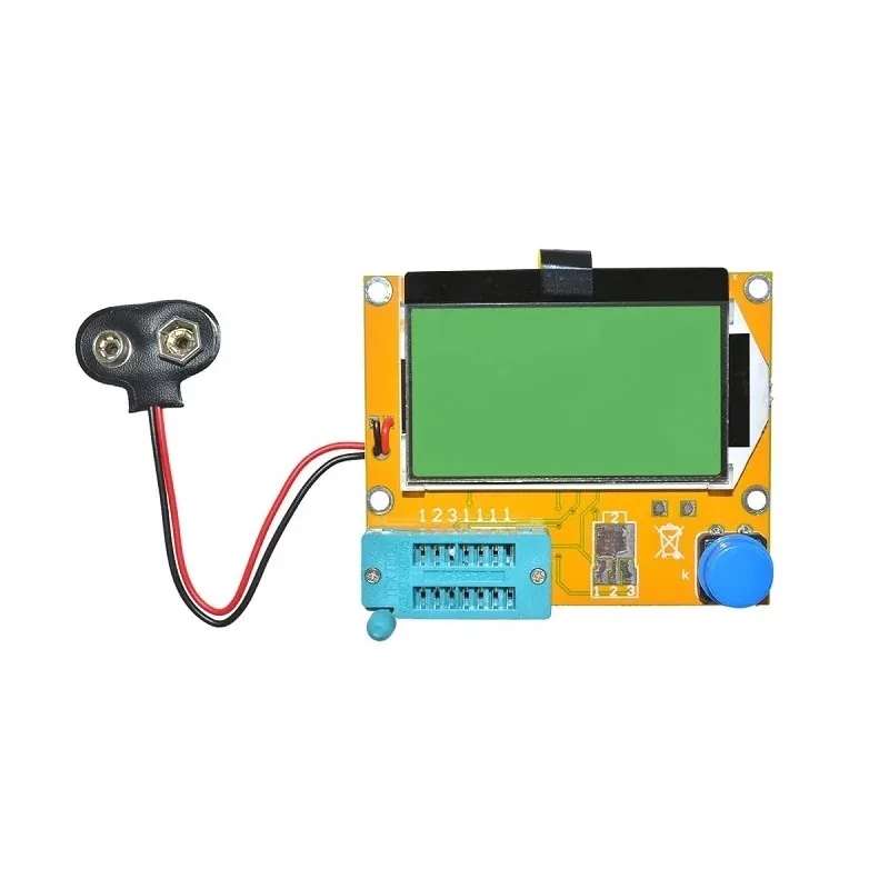
LCR-T4 Transistor Tester & Component Analyser
Measure inductance, capacitance, and ESR of your wound coils. Essential for verifying winding parameters after completing your high-frequency inductors.
Frequently Asked Questions
Q: Can I make my own litz wire from enamelled magnet wire?
Yes — this is called a “DIY litz” approach. Take 20–50 strands of thin enamelled wire (0.1–0.2 mm diameter), twist them together by fixing one end and rotating the other. The twist pitch should be roughly 5–10× the bundle diameter. This works reasonably well for frequencies up to 200–300 kHz and is far cheaper than commercial litz wire for hobbyist use in India.
Q: At what frequency should I switch from solid to litz wire?
A practical rule: when the wire diameter exceeds twice the skin depth, consider litz wire. For 1 mm solid copper wire, this crossover occurs around 5–8 kHz. For 0.5 mm wire, it is around 20–30 kHz. Most SMPS designers switch to litz wire above 50 kHz regardless of wire gauge.
Q: Is litz wire available in India?
Commercial litz wire in India is primarily available through specialty electronics importers and winding wire suppliers in industrial cities like Pune, Chennai, and Coimbatore. For small quantities, it can be ordered from international online stores. Alternatively, DIY litz made from fine enamelled copper wire (available locally) is a practical substitute for hobbyist-scale projects.
Q: How does litz wire affect transformer efficiency?
In a well-designed SMPS transformer at 100 kHz switching frequency, replacing solid copper with properly specified litz wire can reduce copper losses by 60–80%, improving overall converter efficiency by 1–3 percentage points. For a 100W converter, that is 1–3W less heat — significant in a compact enclosure operating in India’s hot climate.
Q: Does the enamel colour of magnet wire indicate anything?
Yes — enamel colour often correlates with the insulation type. Polyurethane (PU) enamel is typically red/brown and strips at soldering temperature. Polyesterimide (PEI/PE) is typically orange/green and requires higher stripping temperatures (above 400°C) or abrasive removal. PU is generally preferred for litz wire applications because it allows easy soldering termination.
Zbotic stocks fine enamelled copper wire, soldering tools, and component testing equipment to support your high-frequency winding projects. Order online with fast delivery across India.


Add comment