
Every robotics builder eventually wants smoother, more precise motion from their motors. Whether you are building a robotic arm, a pan-tilt camera system, or a CNC axis, the answer is almost always the same: PID control. Proportional-Integral-Derivative control is the foundational algorithm that makes motors move smoothly to a target position and hold it there against external forces. This guide takes you from theory to working Arduino code, with practical tuning techniques that actually work.
Why PID for Servo Control?
Consider the simplest approach to motor positioning: turn the motor on until it reaches the target, then turn it off. What actually happens? The motor overshoots the target due to inertia, oscillates back and forth, and eventually settles — but slowly and with poor accuracy under varying loads.
PID control solves this elegantly. It continuously calculates how far the motor is from the target (the error) and adjusts the motor drive signal based on three terms that together produce fast, smooth, stable positioning:
- P — responds proportionally to current error (how far off are we right now?)
- I — responds to accumulated error over time (have we been offset for a long time?)
- D — responds to the rate of change of error (are we approaching the target too fast?)
A well-tuned PID controller can move a motor to a target in the minimum time without overshoot, hold position against gravity or friction, and recover from disturbances quickly. It is the same algorithm used in industrial servo drives, aircraft autopilots, temperature controllers, and the anti-lock braking system in your car.
Understanding P, I, and D Components
Proportional (P) Term
The proportional term is simple: P_output = Kp × error. If the motor is 100 units from the target, the output is Kp × 100. If it is 10 units away, the output is Kp × 10. The closer the motor gets to the target, the less drive force it receives.
The problem with P-only control: as the motor approaches the target and error decreases, the drive force also decreases. The motor never quite reaches the target because when it does, there is zero drive force — any friction or gravity load will hold it slightly off. This residual error is called steady-state error.
Increasing Kp reduces steady-state error but eventually causes oscillation: the motor overshoots, then the large negative error drives it back past the target, and it oscillates around the setpoint indefinitely.
Integral (I) Term
The integral term accumulates error over time: I_output = Ki × ∫error dt (in discrete form: Ki × sum of all past error values × sample time). If the motor sits slightly below target for a long time, the integral term builds up until it is large enough to overcome friction or gravity and push the motor to the target. This eliminates steady-state error.
Too much integral gain causes oscillation — the accumulated error takes time to dissipate after the motor reaches target, so it overshoots and oscillates. The integral term also has a dangerous failure mode called integral windup (covered in detail below).
Derivative (D) Term
The derivative term responds to the rate of change of error: D_output = Kd × d(error)/dt (in discrete form: Kd × (current error – previous error) / sample time). It acts as a brake: when the motor is approaching the target quickly (large negative rate of error change), the D term opposes the motion, slowing it down before it overshoots.
Think of D as a damper. A car suspension without a damper (shock absorber) bounces for a long time after a bump. Adding a damper prevents the bounce. Derivative gain in a PID loop does the same thing — it "damps" the oscillation caused by the P and I terms.
The downside: the derivative term amplifies noise. Any noise in your position sensor signal becomes sharp spikes in the derivative, causing erratic motor commands. Always filter your sensor signal before computing the derivative.
Hardware Requirements
To build a PID servo control system with Arduino, you need:
- Arduino Uno, Mega, or Nano — the microcontroller running the PID algorithm
- DC motor with encoder — the motor to control. The encoder provides position feedback. A gear motor with quadrature encoder is ideal.
- Motor driver — an H-bridge to drive the motor (L298N, BTS7960, or similar based on your motor’s current requirement)
- Power supply — motor supply (typically 6–24 V) and Arduino supply (5 V or via USB)
- Optional: potentiometer — as an analog setpoint input for interactive position control
Alternatively, for hobby servo PID control (using an SG90 or MG996 servo as the actuator with a potentiometer as position feedback), you only need the Arduino, the servo, and a pot — the servo’s internal circuit already handles the power stage.
Wiring the System
For a DC gear motor with encoder and L298N driver:
Component        Pin/Wire     →   Arduino
─────────────────────────────────────────────
Encoder Channel A              →   Pin 2 (interrupt)
Encoder Channel B              →   Pin 3 (interrupt)
Encoder VCC                    →   5V
Encoder GND                    →   GND

L298N ENA (PWM enable)         →   Pin 9 (PWM)
L298N IN1 (direction)          →   Pin 4
L298N IN2 (direction)          →   Pin 5
L298N GND                      →   GND
L298N +5V (logic)              →   5V
L298N Motor power (VMS)        →   12V supply +
L298N GND (power)              →   12V supply -
L298N OUT1/OUT2                →   Motor terminals

Setpoint potentiometer         →   A0 (optional)
Complete Arduino PID Code
Below is a complete, working PID position controller for a DC motor with quadrature encoder:
// Servo Motor PID Control with Arduino
// Zbotic.in — Motors & Actuators Guide

// Motor driver pins (L298N)
const int ENA = 9;   // PWM speed
const int IN1 = 4;   // Direction
const int IN2 = 5;   // Direction

// Encoder pins (interrupt-capable)
const int ENC_A = 2;
const int ENC_B = 3;

// PID gains — tune these for your motor+load
float Kp = 2.0;
float Ki = 0.05;
float Kd = 0.8;

// State variables
volatile long encoderCount = 0;  // Updated by interrupt
long targetPosition = 0;
float integral = 0;
float prevError = 0;
const float INTEGRAL_LIMIT = 1000.0;  // Anti-windup limit

unsigned long lastTime = 0;
const unsigned long SAMPLE_MS = 10;   // 10ms = 100Hz control loop

void setup() {
  pinMode(ENA, OUTPUT);
  pinMode(IN1, OUTPUT);
  pinMode(IN2, OUTPUT);

  pinMode(ENC_A, INPUT_PULLUP);
  pinMode(ENC_B, INPUT_PULLUP);

  // Attach interrupts on both encoder channels
  attachInterrupt(digitalPinToInterrupt(ENC_A), encoderISR_A, CHANGE);
  attachInterrupt(digitalPinToInterrupt(ENC_B), encoderISR_B, CHANGE);

  Serial.begin(115200);
  Serial.println("PID Servo Controller Ready");
}

// Encoder interrupt handlers
void encoderISR_A() {
  if (digitalRead(ENC_A) == digitalRead(ENC_B)) encoderCount++;
  else encoderCount--;
}

void encoderISR_B() {
  if (digitalRead(ENC_A) != digitalRead(ENC_B)) encoderCount++;
  else encoderCount--;
}

void setMotor(int pwm) {
  // pwm: -255 to +255 (negative = reverse)
  pwm = constrain(pwm, -255, 255);
  if (pwm > 0) {
    digitalWrite(IN1, HIGH);
    digitalWrite(IN2, LOW);
    analogWrite(ENA, pwm);
  } else if (pwm < 0) {
    digitalWrite(IN1, LOW);
    digitalWrite(IN2, HIGH);
    analogWrite(ENA, -pwm);
  } else {
    // Brake: both direction pins LOW
    digitalWrite(IN1, LOW);
    digitalWrite(IN2, LOW);
    analogWrite(ENA, 0);
  }
}

void pidUpdate() {
  unsigned long now = millis();
  if (now - lastTime < SAMPLE_MS) return;
  float dt = (now - lastTime) / 1000.0;  // seconds
  lastTime = now;

  // Read current position (atomic read for volatile)
  long currentPos;
  noInterrupts();
  currentPos = encoderCount;
  interrupts();

  // Compute error
  float error = (float)(targetPosition - currentPos);

  // Integral with anti-windup clamping
  integral += error * dt;
  integral = constrain(integral, -INTEGRAL_LIMIT, INTEGRAL_LIMIT);

  // Derivative (on error, simple difference)
  float derivative = (error - prevError) / dt;
  prevError = error;

  // PID output
  float output = (Kp * error) + (Ki * integral) + (Kd * derivative);

  setMotor((int)output);

  // Debug output
  Serial.print("Pos:"); Serial.print(currentPos);
  Serial.print(" Target:"); Serial.print(targetPosition);
  Serial.print(" Err:"); Serial.print(error);
  Serial.print(" Out:"); Serial.println(output);
}

void loop() {
  // Example: move to positions 0, 500, 1000, 500, repeat
  targetPosition = 0;    delay(3000); pidLoop();
  targetPosition = 500;  delay(3000); pidLoop();
  targetPosition = 1000; delay(3000); pidLoop();
  targetPosition = 500;  delay(3000); pidLoop();
}

void pidLoop() {
  // Run PID for the duration while waiting
  unsigned long start = millis();
  while (millis() - start < 3000) {
    pidUpdate();
  }
}
Tuning PID Gains Step by Step
The Ziegler-Nichols tuning method is a classic starting point, but for a practical motor system, manual iterative tuning is usually faster:
- Start with Ki = 0 and Kd = 0. Increase Kp slowly until the motor reaches the target position (or gets close). You will see some overshoot and oscillation — this is expected at this stage.
- Reduce Kp until oscillation stops. The motor should now reach the target without bouncing, but there may be residual steady-state error (it stops slightly short of target).
- Add a small Ki. Start with Ki = Kp / 100. The motor should now eliminate the steady-state error. If it oscillates, reduce Ki or reduce Kp slightly.
- Add Kd to reduce overshoot. Start with Kd = Kp / 10. Slowly increase until overshoot disappears and the motor moves sharply to the target without bouncing.
- Final refinement: Once the system is stable, gradually increase all gains together (scale factor of 1.1–1.2 at a time) to achieve faster response. Stop when oscillation begins to reappear, then back off 10–20%.
Common signs and remedies during tuning:
- Motor oscillates continuously: Kp too high. Reduce Kp by 30–50%.
- Motor reaches target slowly and never quite gets there: Add or increase Ki.
- Motor overshoots badly but is stable: Increase Kd.
- Motor output chatters rapidly (high-frequency noise): Kd too high, or encoder noise. Low-pass filter the encoder count or reduce Kd.
- Motor slams to position then slowly backs off: Integral windup — see below.
Integral Windup: The Hidden Problem
Integral windup is one of the most common PID implementation mistakes. It occurs when the motor is asked to move a large distance: while the motor is moving toward the target, the error remains large, and the integral term accumulates (winds up) to a very large value. When the motor finally reaches the target, the integral term is so large that even with error = 0, the total PID output continues to drive the motor past the target. The motor overshoots badly, then oscillates as the integral slowly unwinds.
Prevention strategies:
- Clamp the integral: Limit the integral to ±INTEGRAL_LIMIT as shown in the code. Set the limit to approximately 255/Ki to prevent the integral alone from saturating the output.
- Conditional integration: Only integrate when the output is not saturated — if the motor is already at maximum PWM (255), additional integration cannot help and only winds up.
- Back-calculation anti-windup: Subtract a portion of the difference between actual and saturated output back from the integral at each step. This is the most mathematically principled approach.
- Reset integrator on large setpoint changes: If the setpoint jumps by more than a threshold, clear the integral to zero and let it build up fresh.
Derivative Kick and Noise Filtering
Derivative kick is a sudden spike in output that occurs when the setpoint changes suddenly. Because the derivative is computed on the error, and error changes instantly when the setpoint jumps, the derivative term spikes to a very large value for one sample period. This causes the motor to lurch.
Solutions:
- Derivative on measurement (not error): Compute the derivative as
Kd × -(current_position - prev_position) / dtinstead ofKd × (error - prev_error) / dt. Since position changes smoothly, there is no kick when the setpoint changes. - Low-pass filter on derivative: Apply a simple first-order filter:
filtered_D = alpha × raw_D + (1-alpha) × filtered_D_prev. A value of alpha = 0.1–0.3 significantly reduces noise without adding much lag. - Setpoint ramping: Instead of jumping the setpoint instantly, ramp it smoothly to the new target. This reduces both derivative kick and the overall demand on all PID terms.
Hobby Servo vs DC Motor Servo
It is worth distinguishing two different scenarios for "servo motor PID with Arduino":
Scenario 1: Hobby servo (SG90, MG996) — These already have a complete PID servo loop inside them. You just send a PWM signal (1–2 ms pulse, 50 Hz) and the internal circuit moves to the commanded angle. The external PID described in this guide is not needed unless you are implementing a higher-level cascade controller (outer position loop controlling the inner servo loop). For most projects, just use the Arduino Servo library.
Scenario 2: DC motor + encoder — This is where the PID controller described in this article applies. You are implementing the position control loop in Arduino firmware because there is no internal controller in the motor. This is the more powerful and flexible approach, used in robot arms, CNC axes, and automated positioning systems.
Advanced Techniques
Cascade PID (Velocity Inner Loop)
For very precise positioning with fast motors, a cascade (nested) PID is used: the outer position loop computes a target velocity, and the inner velocity loop controls the motor current to achieve that velocity. This separates the bandwidth of position and velocity control, allowing faster overall response. The inner loop runs at 1–10 kHz; the outer loop at 100–500 Hz.
Feedforward Control
Add a feedforward term that anticipates the required motor output based on the desired velocity or acceleration profile, bypassing the feedback loop for the predictable portion of the motion. This dramatically improves tracking accuracy during fast movements.
Trapezoidal Motion Profile
Instead of commanding the motor to jump to a new setpoint instantly, generate a smooth trapezoidal velocity profile: accelerate at a defined rate, cruise at maximum velocity, then decelerate to stop at the target. Feed this profile as a continuously moving setpoint to the PID controller. The motor follows the profile smoothly without asking the PID to handle large instantaneous errors.
Product Recommendations
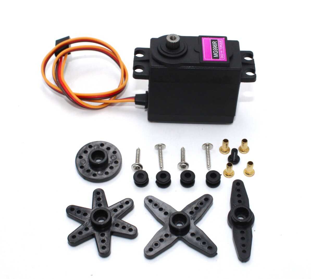
Servo MG996 13KG 180 Degree — High Quality
A robust metal-gear hobby servo producing 13 kg-cm torque. Perfect for robot arm joints where you need high torque and the servo’s internal PID is sufficient. Use directly with Arduino’s Servo library.
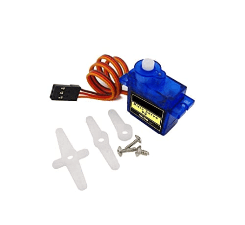
TowerPro SG90 180 Degree Rotation Servo Motor
The classic micro servo for Arduino beginners and prototypers. Its light weight and direct PWM control make it ideal for learning servo control concepts before advancing to DC motor PID systems.
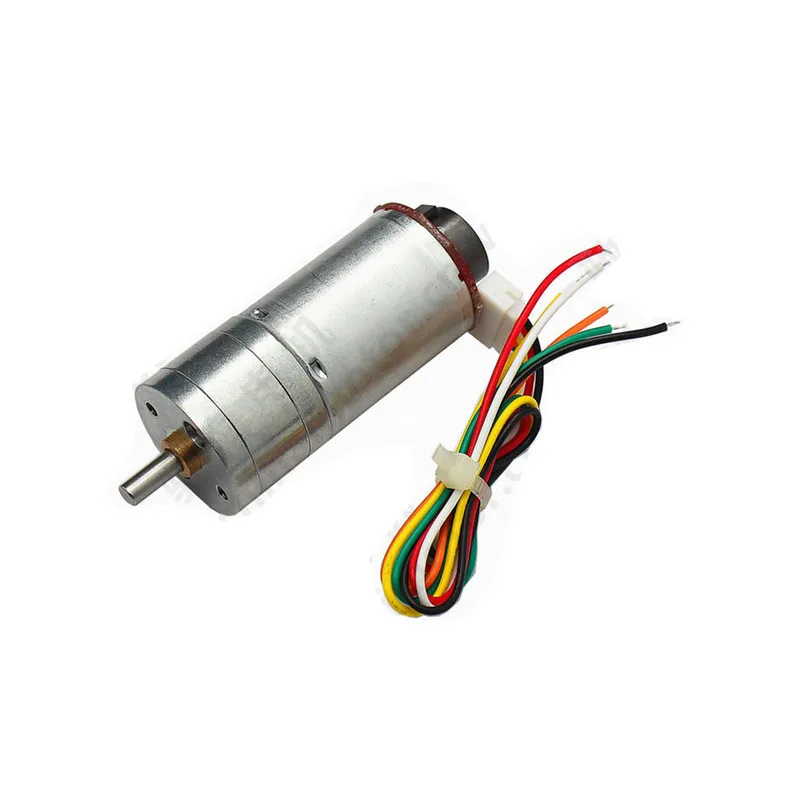
25GA-370 12V 12RPM DC Gear Motor with Encoder
The ideal motor for practising DC motor PID control. The built-in quadrature encoder provides the position feedback your PID controller needs, while the gearbox keeps speeds manageable for learning.
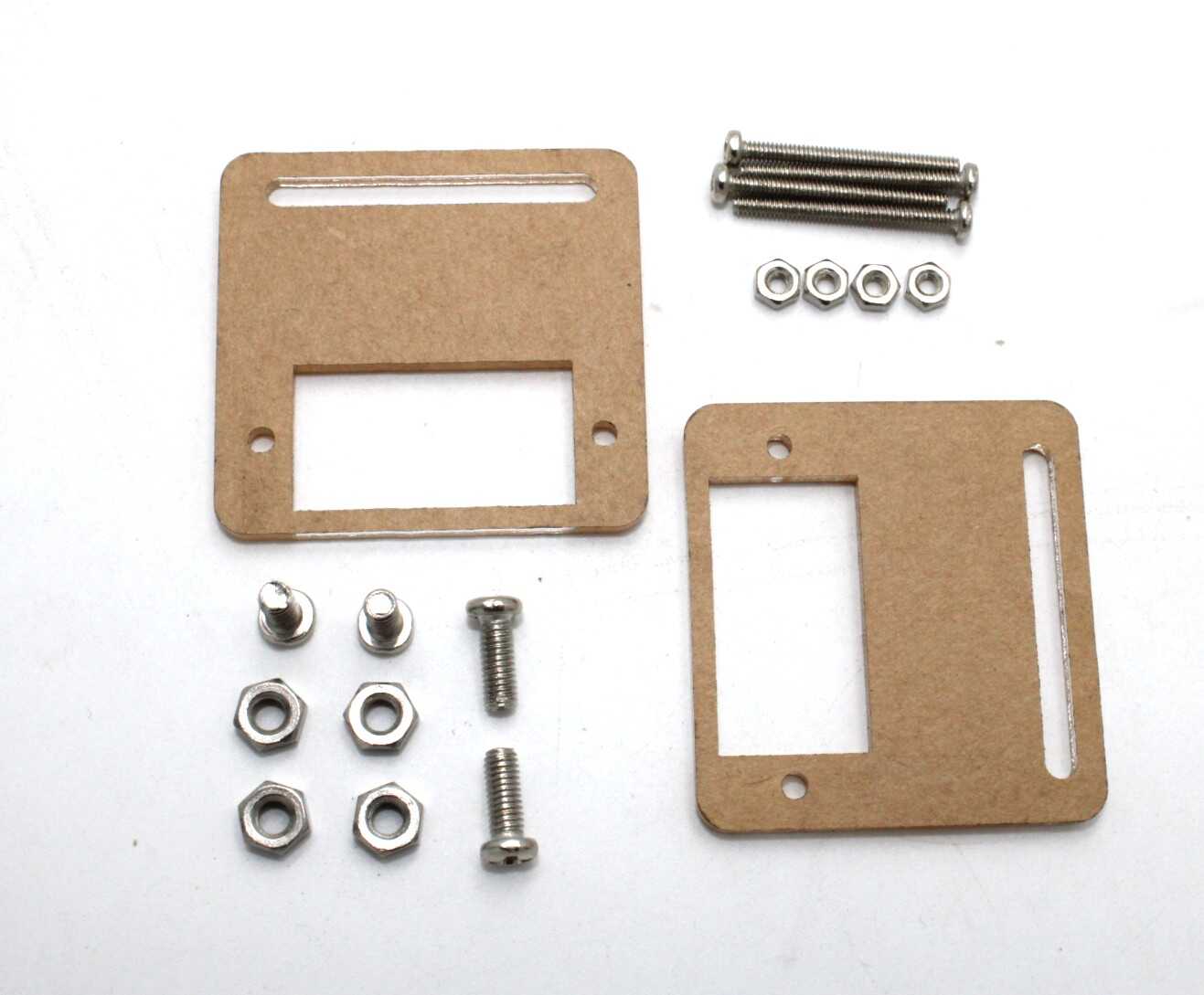
Servo Mount Holder Bracket for SG90/MG90 — Pack of 2
Proper mechanical mounting is as important as the control algorithm. These brackets let you securely mount SG90/MG90 servos for pan-tilt systems, robot joints, and any application where the servo must resist reaction forces.
Frequently Asked Questions
What is the difference between PID and on-off control?
On-off control (bang-bang control) simply turns the motor fully on when below target and fully off when at or above target. It causes constant oscillation around the setpoint. PID control varies the motor drive continuously based on the error magnitude, rate, and history, producing smooth, accurate positioning without oscillation when properly tuned.
How fast should my PID loop run?
The control loop should run at least 10× faster than the mechanical bandwidth of your system (roughly, how fast the motor and load can physically move). For typical small robot motors, 100 Hz (every 10 ms) is a good starting point. For faster motors or tighter control, 500 Hz or 1 kHz may be needed. The Arduino Uno’s main loop can run PID at 1–2 kHz for a simple implementation.
Can I use PID without an encoder?
Yes, with position feedback from an alternative sensor. A potentiometer wired to the motor shaft works for limited-range positioning (like a throttle body or valve actuator). An ultrasonic sensor or IR distance sensor can provide position feedback for a linear moving platform. The PID algorithm is the same regardless of sensor type — only the feedback signal changes.
Why does my motor hunt (oscillate) around the setpoint even with small gains?
Motor dead zone is a common cause: at very low PWM values (typically under 30–50 out of 255), the motor does not move due to stiction and friction. The PID increases output until the motor suddenly jumps, overshoots, and the cycle repeats. Solutions: add a dead-band around the setpoint where output is clamped to zero, or implement a feed-forward bias that always adds a small base PWM to overcome stiction in the correct direction.
What is the difference between position PID and velocity PID?
Position PID controls where the motor shaft is (target: encoder count). Velocity PID controls how fast the motor shaft is spinning (target: RPM or counts/second). For servo positioning you use position PID. For constant-speed conveyor or wheel drive you use velocity PID. Cascade control uses both: an outer position PID whose output is the setpoint for an inner velocity PID.
Should I use Arduino’s analogWrite frequency for PID, or a higher PWM frequency?
For most gear motors, Arduino’s default 490–980 Hz PWM is fine. If you hear a high-pitched whine at the PWM frequency, increase it above 20 kHz (inaudible). Note that changing Timer 0 affects millis(). On Arduino Mega, use Timer 1, 3, 4, or 5 for PWM frequency changes without affecting system timing functions.
Zbotic stocks servo motors from the micro SG90 to the powerful MG996, DC gear motors with encoders, motor drivers, and all the electronics you need. Order online with fast delivery across India.


Add comment