
Relays are among the oldest and most reliable components in electronics — and they remain indispensable today. Found in everything from Arduino home automation projects to automotive electronics and industrial control systems, a relay allows a small electrical signal to control a much larger load with complete electrical isolation. This guide explains the complete relay working principle, how its coil and contacts function, and why a back-EMF protection diode is absolutely non-negotiable in any relay circuit.
What Is a Relay?
A relay is an electrically operated switch. It uses an electromagnet (coil) to mechanically move a set of contacts, switching a separate circuit on or off. The fundamental advantage of a relay is galvanic isolation — the control circuit (low voltage) and the load circuit (high voltage) are completely electrically separate, connected only through magnetic force.
This isolation makes relays ideal for:
- Switching 230V AC mains loads from a 5V microcontroller
- Controlling high-current DC loads (motors, heaters, solenoids)
- Providing safety isolation in automotive and industrial equipment
- Creating fail-safe circuits where a de-energised relay defaults to a safe state
- Latching circuits where a brief pulse maintains a switch position
The most common type used in hobbyist and Arduino projects is the electromechanical relay (EMR) — a physical switching device. Solid-state relays (SSR) use semiconductors instead of mechanical contacts and are suited for high-frequency switching, but EMRs are more flexible and easier to understand as a starting point.
Relay Working Principle: Step by Step
Here is how an electromagnetic relay operates, from input signal to output switching:
- Control signal applied: A voltage (typically 5V, 12V, or 24V depending on relay rating) is applied across the coil terminals
- Coil energises: Current flows through the wire coil, generating a magnetic field around the iron core (electromagnet)
- Armature attracted: The magnetic field pulls a movable metal arm called the armature toward the iron core
- Contacts switch: The armature’s movement physically pushes the moving contact (common) from the normally closed (NC) position to the normally open (NO) position
- Load circuit changes state: The load connected to the relay contacts is now switched on (if connected to NO) or off (if connected to NC)
- Spring return: When the control voltage is removed, the magnetic field collapses, and a return spring pulls the armature back to its original position, returning contacts to their default state
The entire mechanical switching happens in milliseconds — typically 5-15ms for energisation and 3-8ms for release on common relay types.
The Relay Coil: Magnetic Actuation
The coil is the heart of an electromagnetic relay. It consists of hundreds to thousands of turns of insulated copper wire wound around a soft iron core. When current flows through the coil, the core becomes a powerful electromagnet.
Coil Voltage and Current
Every relay coil has a rated voltage (called the coil voltage or nominal voltage). Common ratings for hobbyist relays include:
- 5VDC — Direct compatibility with Arduino and most microcontrollers
- 12VDC — Common in automotive and general industrial use
- 24VDC — Industrial control panels
- 230VAC — Some industrial relays, but AC coil relays are less common in hobbyist use
The coil draws a specific current when energised — typically 60-180mA for small 5V relays. This current is well beyond what a microcontroller GPIO pin can supply (typically 20-40mA max). This is why a transistor driver is always needed between a microcontroller and a relay coil.
Coil Resistance
Relay coil resistance is specified in the datasheet. For a 5V relay drawing 100mA: R = 5V / 0.1A = 50Ω. For a 12V relay drawing 80mA: R = 12V / 0.08A = 150Ω. You can measure coil resistance with a multimeter to verify a relay’s health and confirm its rated voltage.
Pull-in and Drop-out Voltage
Relays have two important voltage thresholds:
- Pull-in voltage: Minimum voltage at which the relay reliably closes (~75% of nominal)
- Drop-out voltage: Voltage at which the relay releases (~25% of nominal)
This hysteresis means once a relay closes, it stays closed even if voltage drops below the pull-in threshold — it only releases at the much lower drop-out voltage. This is important for noise-immune relay circuits.
Relay Contacts: NO, NC, and COM
The contacts are the switching elements of the relay. A basic single-pole double-throw (SPDT) relay has three contact terminals:
- COM (Common): The moving contact, connected to the load
- NO (Normally Open): Open when relay is de-energised, CLOSED when relay energises
- NC (Normally Closed): CLOSED when relay is de-energised, open when relay energises
The terminology “normally” refers to the state when no power is applied to the coil. This is important for safety design:
- If you want a load to be OFF when the controller loses power: use the NO contact (load is off in the relay’s default/rest state)
- If you want a load to remain ON when the controller loses power (fail-safe ON): use the NC contact
For example, a fire alarm system’s sounder might be connected to NC so that a power failure activates the alarm rather than silencing it — this is a fail-safe design using the relay’s NC contact.
Relay Configurations
- SPST (Single Pole Single Throw): One COM, one NO or NC contact. Simplest type.
- SPDT (Single Pole Double Throw): One COM, one NO and one NC. Most common in hobbyist modules.
- DPDT (Double Pole Double Throw): Two independent sets of SPDT contacts, switched simultaneously by one coil. Used for motor direction control or switching two circuits together.
Understanding Relay Contact Ratings
Contact ratings define what loads the relay can safely switch. They are specified separately for AC and DC because AC arcs extinguish naturally at zero crossing, while DC arcs are much harder to break:
| Relay Type | AC Rating | DC Rating | Typical Use |
|---|---|---|---|
| SRD-05VDC-SL-C (HF3FD) | 10A / 250VAC | 10A / 30VDC | Arduino relay modules, home automation |
| G5LE-1 (OMRON) | 10A / 250VAC | 10A / 30VDC | General purpose switching |
| Automotive relay (ISO) | — | 30A / 12VDC | Vehicle headlights, horns, fans |
Always derate relay contacts by 20-30% from the rated maximum for reliable long-term operation. For high-inrush loads like motors, lamps (cold filament spike), or capacitive loads, derate more aggressively — to 50% or use relays with a higher contact rating.
Back-EMF: The Hidden Danger
This is the section most beginners skip — and then wonder why their microcontroller keeps resetting or their transistors keep dying.
A relay coil is an inductor. Inductors oppose changes in current. When you suddenly cut power to the coil (by switching the transistor OFF), the magnetic field collapses almost instantaneously. The collapsing field generates an enormous voltage spike in the opposite direction — this is back-EMF (also called inductive kickback or flyback voltage).
How large is this spike? The voltage generated is V = L × (dI/dt). If a coil with L = 50mH has its 100mA current cut in 1 microsecond:
V = 0.05H × (0.1A / 0.000001s) = 0.05 × 100,000 = 5,000 volts
In practice, parasitic circuit resistance and capacitance limit this to perhaps 50-200V in a typical relay circuit — but that’s still catastrophically lethal for a transistor rated at 30V. Without protection, the transistor driving the relay will fail within a few switching cycles (sometimes the very first time).
The Flyback Diode: How It Protects Your Circuit
The flyback diode (also called a snubber diode, freewheeling diode, or suppressor diode) is placed across the relay coil in reverse bias under normal operation:
- Diode anode → coil negative terminal
- Diode cathode → coil positive terminal (supply rail)
During normal operation (relay energised), the diode is reverse-biased by the supply voltage and does nothing. When the transistor switches off, the back-EMF spike appears. Because the spike is in the opposite polarity to the supply, it now forward-biases the diode, providing a low-resistance path for the collapsing coil current to circulate. The energy dissipates safely in the coil’s own resistance and the diode’s small forward voltage.
Which diode to use?
- 1N4007: The classic choice. 1A, 1000V PIV. More than adequate for any relay circuit. Cheap and universally available.
- 1N4148: Signal diode, 200mA. Works for small 5V relays but not recommended for larger relays.
- 1N5819 (Schottky): Faster switching, lower forward voltage (0.3V vs 0.7V). Better suppression, but more expensive.
The 1N4007 is the default recommendation for all relay flyback protection in hobby circuits. One diode per relay coil, placed as close to the relay as possible to minimise the loop area of the transient current path.
Driving a Relay with a Transistor
Since microcontroller GPIO pins cannot supply the 60-180mA needed to energise a relay coil, a transistor is used as an amplifier/switch between the GPIO and the relay.
Here is the standard NPN transistor relay driver circuit:
5V GPIO → 1kΩ resistor → Base of NPN (e.g. BC547)
Collector of NPN → Relay coil negative terminal
Relay coil positive terminal → 5V supply
Emitter of NPN → GND
1N4007 flyback diode: Anode to Collector, Cathode to 5V supply
(across the coil in reverse bias)
Base resistor calculation:
- Relay coil current (Ic): typically 100mA for 5V relay
- Transistor hFE: use 10 (conservative saturation factor)
- Required base current: Ib = 100mA / 10 = 10mA
- Base resistor: Rb = (Vgpio – Vbe) / Ib = (5 – 0.7) / 0.01 = 430Ω → use 470Ω or 1kΩ
With a 1kΩ base resistor and 5V GPIO: Ib = (5-0.7)/1000 = 4.3mA. For a relay needing 100mA and BC547 with hFE=200: fully saturates with only 0.5mA base current needed. The 1kΩ provides plenty of base drive while limiting GPIO current.
Controlling Relays with Arduino
The easiest way to use relays with Arduino is with a relay module — a pre-built PCB that includes the transistor driver, flyback diode, and often an optocoupler for extra isolation. These modules are available in 1, 2, 4, 8, and 16 channel versions.
Most relay modules are active LOW by default (relay energises when the control signal goes LOW, not HIGH). This is because the module uses a PNP or NPN transistor with inverted logic. Always check your module’s datasheet or test with a simple HIGH/LOW sketch.
Basic Arduino relay control sketch:
const int RELAY_PIN = 7;

void setup() {
  pinMode(RELAY_PIN, OUTPUT);
  digitalWrite(RELAY_PIN, HIGH); // Start with relay OFF (active LOW module)
}

void loop() {
  digitalWrite(RELAY_PIN, LOW);  // Relay ON
  delay(1000);
  digitalWrite(RELAY_PIN, HIGH); // Relay OFF
  delay(1000);
}
Safety note when using relays with mains voltage (230V AC): Always ensure the high-voltage side is fully contained in a proper enclosure. Never work on the mains side of a relay while the circuit is powered. Use appropriately rated wire (minimum 1mm² for 10A loads) on the AC side.
Relay vs MOSFET: When to Use Each
| Feature | Relay (EMR) | MOSFET |
|---|---|---|
| AC load switching | Yes (native) | No (needs triac or SSR) |
| High DC current | Yes (up to 30A+) | Yes (with heatsink) |
| Switching speed | Slow (5-15ms) | Very fast (nanoseconds) |
| Electrical isolation | Complete (galvanic) | None (shared ground) |
| Mechanical wear | Yes (100k-10M cycles) | None |
| PWM compatible | No | Yes (ideal for PWM) |
| Voltage drop | Very low (milliohm contacts) | Low (Rds_on) |
| Cost | Low | Low to moderate |
Use a relay when: switching AC mains, you need galvanic isolation, the load current is very high, or switching speed is not critical.
Use a MOSFET when: you need PWM control (motor speed, LED dimming), fast switching, or the application is pure DC at moderate voltages.
Recommended Products from Zbotic
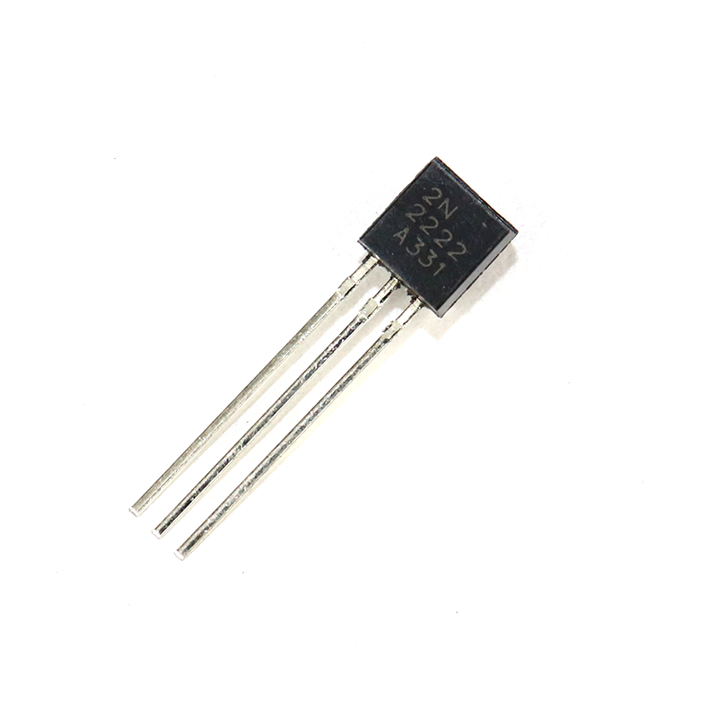
2N2222 NPN Transistor (Pack of 20)
The go-to transistor for building relay driver circuits. The 2N2222 handles 600mA collector current — more than enough to drive any standard 5V or 12V relay coil.
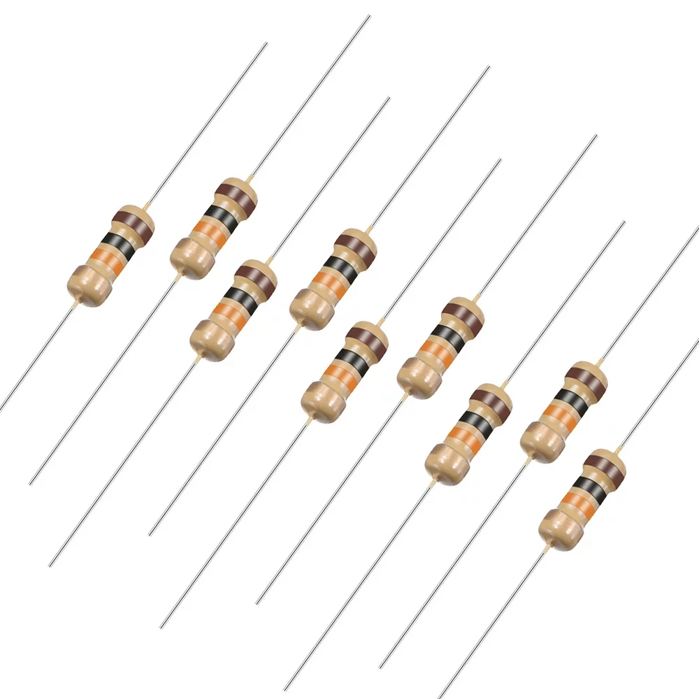
10 Ohm 0.25W Carbon Film Resistor (Pack of 50)
Use 470Ω or 1kΩ base resistors (from a resistor kit) for your transistor relay driver. These carbon film resistors are perfectly suited for base drive limiting in relay circuits.
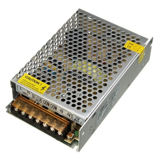
12V 10A SMPS – 120W DC Metal Power Supply
A reliable 12V supply for powering relay coils and DC loads in automation projects. The 10A capacity handles multiple relay coils and their loads simultaneously.

10CM Male To Female Breadboard Jumper Wires 2.54MM – 40Pcs
Connect your Arduino to relay modules cleanly with these male-to-female jumper wires. Perfect for signal lines between the microcontroller and relay control pins.
Frequently Asked Questions
Q: Why does my Arduino reset every time I switch the relay?
A: This is almost certainly back-EMF without proper flyback diode protection. The voltage spike from the collapsing coil injects noise or direct voltage onto the power supply lines, causing the microcontroller to brownout reset. Solution: Add a 1N4007 diode across the relay coil (cathode to positive terminal). Also, add a 100µF decoupling capacitor across the power supply input to the relay coil.
Q: Can I drive a relay directly from an Arduino GPIO pin?
A: No. Arduino GPIO pins are rated for 40mA maximum (20mA recommended continuous). Standard relay coils draw 60-180mA. Driving a relay directly from GPIO risks damaging the microcontroller’s output driver. Always use a transistor (NPN BJT or N-channel MOSFET) between the GPIO and the relay coil.
Q: What is the difference between NO and NC relay contacts?
A: NO (Normally Open) contacts are open (disconnected) when the relay coil is not energised, and they close when the coil is energised. NC (Normally Closed) contacts are closed (connected) when the coil is not energised, and they open when energised. Use NO when you want the load to be OFF by default; use NC when you need the load to remain ON if power to the controller is lost.
Q: How long does a relay last?
A: Mechanical relay contact life is specified in switching cycles. Most small PCB relays are rated for 100,000 to 1,000,000 electrical operations. At 10 switches per day, a 100,000-cycle relay lasts ~27 years. For high-cycle applications (switching dozens of times per minute), consider solid-state relays (SSR) which have effectively unlimited switching life.
Q: Can I use a relay for motor speed control?
A: No. Relay contacts are mechanical and can only switch at a few times per second before wear becomes excessive. PWM motor speed control requires switching at 1-50kHz, which is impossible with mechanical relays. For motor speed control, use a MOSFET H-bridge driver. Relays are suitable only for ON/OFF motor control (start/stop) or direction reversing (using a DPDT relay).
Q: My relay makes a loud clicking noise — is this normal?
A: Yes. The click is the sound of the armature moving to close or open the contacts. This is completely normal for electromechanical relays. If you need quiet operation (in a bedroom automation project, for example), consider solid-state relays or MOSFET-based switching, which operate silently.


Add comment