
Introduction
If you have ever wondered how your phone charger or DC power supply converts AC mains power into smooth DC voltage, the answer lies in rectifier circuits types. A rectifier is one of the most fundamental building blocks of electronics — converting alternating current (AC) into direct current (DC). Whether you are a student, a hobbyist building your first power supply, or a maker designing a custom circuit board in India, understanding rectifiers is an absolute must. In this guide, we will walk you through all three major rectifier circuit types — half wave, full wave (centre-tap), and bridge — with clear explanations, diagrams in text, calculations, and practical tips.
Table of Contents
- What is a Rectifier Circuit?
- Half Wave Rectifier: How It Works
- Full Wave Rectifier (Centre-Tap): Explained
- Bridge Rectifier: The Most Popular Choice
- Comparison Table: Half Wave vs Full Wave vs Bridge
- Filtering the Ripple: Capacitor and LC Filters
- Practical Applications and Project Ideas
- Frequently Asked Questions
What is a Rectifier Circuit?
A rectifier circuit is an electronic circuit that converts AC (alternating current), which periodically reverses direction, into DC (direct current), which flows in one direction only. This conversion is essential because most electronic components — microcontrollers, sensors, ICs, LEDs — require a stable DC supply to function properly.
The core component of any rectifier is the diode, a semiconductor device that allows current to flow in only one direction. When a diode is forward biased (anode positive, cathode negative), it conducts current. When reverse biased, it blocks current. This property is exploited in rectifier circuits to block the negative half of the AC waveform, or to flip it into a positive direction.
The output of a basic rectifier is called pulsating DC — it is DC in the sense that it never goes negative, but it still fluctuates in amplitude. A smoothing capacitor or LC filter is typically added after the rectifier to reduce this ripple and produce steady DC.

9V Battery Operated LCR-T4 Transistor Tester
Measure resistance, capacitance, and test diodes and transistors for your rectifier circuits instantly. Great for verifying components before soldering.
Half Wave Rectifier: How It Works
The half wave rectifier is the simplest of all rectifier circuits types. It uses a single diode in series with the load.
Working Principle
During the positive half cycle of the AC input, the diode is forward biased and conducts, allowing current to pass through the load resistor. During the negative half cycle, the diode becomes reverse biased and blocks current — so the output is zero for half the cycle.
Key Formulas
- Average (DC) output voltage: VDC = Vm / π ≈ 0.318 × Vm
- RMS output voltage: VRMS = Vm / 2 = 0.5 × Vm
- Ripple frequency: Same as input frequency (50 Hz in India)
- Ripple factor: 1.21 (very high — lots of AC ripple in the output)
- Rectifier efficiency: ~40.6%
- Form factor: 1.57
Advantages of Half Wave Rectifier
- Simplest design — only one diode required
- Very low cost and easy to build on a breadboard
- Good for low-power applications or signal detection
Disadvantages
- Only half the AC waveform is used — very low efficiency
- High ripple factor requires a large filter capacitor
- Not suitable for powering sensitive circuits
- High DC saturation in transformer core (if used with a transformer)
Where it is used: Simple battery chargers, signal demodulators, low-cost power supplies for non-critical loads.
Full Wave Rectifier (Centre-Tap): Explained
The full wave rectifier overcomes the biggest limitation of the half wave rectifier by converting both halves of the AC waveform into DC. The most common implementation uses a centre-tapped transformer and two diodes.
Working Principle
The centre-tapped transformer has two equal secondary windings connected in series, with the centre tap acting as the common ground reference. During the positive half cycle, D1 conducts and current flows through the load. During the negative half cycle, D2 conducts — but because the winding is flipped relative to the centre tap, current still flows through the load in the same direction. The result is a full-wave pulsating DC with ripple at twice the input frequency (100 Hz in India).
Key Formulas
- Average output voltage: VDC = 2Vm / π ≈ 0.636 × Vm
- RMS output voltage: VRMS = Vm / √2 ≈ 0.707 × Vm
- Ripple frequency: 2 × input frequency = 100 Hz
- Ripple factor: 0.48 (much better than half wave)
- Rectifier efficiency: ~81.2%
Advantages
- Higher efficiency — both halves of AC are utilised
- Lower ripple factor — smaller filter capacitor needed
- No DC saturation in the transformer
Disadvantages
- Requires a centre-tapped transformer (more expensive and bulky)
- PIV (Peak Inverse Voltage) across each diode = 2Vm — diodes must be rated accordingly
- Centre tap is not always available in off-the-shelf transformers
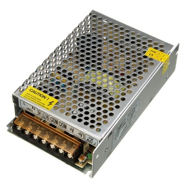
12V 10A SMPS – 120W DC Metal Power Supply
A ready-made regulated DC supply that incorporates modern rectification and filtering internally — ideal for powering your projects without building from scratch.
Bridge Rectifier: The Most Popular Choice
The bridge rectifier is by far the most widely used rectifier circuit type in modern electronics. It uses four diodes arranged in a bridge configuration and does not require a centre-tapped transformer — making it both cheaper and more practical.
Working Principle
The four diodes (D1, D2, D3, D4) are arranged so that during the positive half cycle, D1 and D3 conduct, and during the negative half cycle, D2 and D4 conduct. In both cases, current flows through the load in the same direction. This gives full-wave rectification without needing a special transformer.
Key Formulas
- Average output voltage: VDC = 2Vm / π ≈ 0.636 × Vm (but subtract 2 × 0.7V diode drops)
- RMS output voltage: VRMS = Vm / √2
- Ripple frequency: 100 Hz (double the input, same as centre-tap full wave)
- Ripple factor: 0.48
- Rectifier efficiency: ~81.2%
- PIV per diode: Vm (half that of centre-tap — so cheaper diodes can be used)
Advantages
- No centre-tapped transformer needed — use any standard transformer
- Low PIV per diode — 1N4007 diodes (rated 1000V PIV) are more than adequate for most projects
- Bridge rectifier ICs (e.g. W04, DB107) are available as a single 4-pin package for under ₹10
- Same efficiency as full-wave centre-tap
Disadvantages
- Two diode voltage drops (≈1.4V total) in the output path — slightly lower output voltage
- Four diodes instead of two — but since bridge ICs are cheap, this is rarely a concern
Bridge Rectifier with Capacitor Filter
Adding a large electrolytic capacitor (e.g. 1000µF, 2200µF) across the output dramatically smooths the ripple. The capacitor charges up to the peak voltage and discharges slowly between peaks, maintaining a nearly constant DC output. For a 12V AC transformer (17V peak), a 2200µF/50V capacitor gives well under 1V ripple at moderate loads — perfectly usable for most hobby circuits.

Carbon Film Resistors – Pack of 100
Essential for building test loads and current-limiting circuits when prototyping and testing your rectifier designs on a breadboard.
Comparison Table: Half Wave vs Full Wave vs Bridge
| Parameter | Half Wave | Full Wave (CT) | Bridge |
|---|---|---|---|
| Number of Diodes | 1 | 2 | 4 |
| Transformer Needed | Simple | Centre-Tap | Simple |
| Ripple Factor | 1.21 | 0.48 | 0.48 |
| Ripple Frequency | 50 Hz | 100 Hz | 100 Hz |
| Efficiency | 40.6% | 81.2% | 81.2% |
| PIV per Diode | Vm | 2Vm | Vm |
| Output DC Voltage | 0.318 Vm | 0.636 Vm | 0.636 Vm – 1.4V |
| Typical Use | Simple chargers, signal detectors | Lab power supplies | Most DC power supplies |
Filtering the Ripple: Capacitor and LC Filters
Even after full-wave rectification, the output still has a 100 Hz ripple. For most circuits, you need to smooth this further. Here are the common approaches:
Capacitor Filter (C-Filter)
A large electrolytic capacitor connected in parallel with the load is the simplest and most common filter. The capacitor charges to the peak voltage and discharges slowly through the load between peaks. The ripple voltage (Vr) can be calculated as:
Vr ≈ IL / (f × C)
Where IL is the load current, f is the ripple frequency (100 Hz for full-wave), and C is the capacitance in farads. To achieve 1V ripple at 500mA load: C = 0.5 / (100 × 1) = 5000µF.
RC Filter
Adding a resistor before the capacitor forms a pi-section RC filter. This reduces ripple further but drops some voltage across the resistor. It is suitable for low-current applications where a small voltage drop is acceptable.
LC Filter
An inductor (choke) followed by a capacitor forms an LC filter — the gold standard for low-ripple DC power supplies. The inductor opposes rapid current changes, and the capacitor absorbs residual ripple. LC filters are used in high-quality linear power supplies and audio amplifiers.

0.1µF Ceramic Capacitor – Pack of 50
Use ceramic capacitors as decoupling/bypass capacitors after your rectifier circuit to filter out high-frequency noise. An essential in any power supply design.
Practical Applications and Project Ideas
Understanding rectifier circuits opens the door to a wide range of DIY projects. Here are some practical applications popular with Indian makers and electronics students:
- 5V USB Phone Charger: Bridge rectifier + 7805 voltage regulator. Great first project for beginners. Total component cost under ₹50.
- 12V Lead-Acid Battery Charger: Bridge rectifier with transformer, capacitor filter, and current-limiting resistor. Charges 12V batteries safely.
- DC Bench Power Supply: Bridge rectifier + large filter caps + LM317 adjustable regulator. Output 1.2V to 30V, adjustable. Used in labs all over India.
- LED Driver: Half-wave rectifier with resistive dropper to drive a string of LEDs directly from 230V mains — common in cheap LED bulb designs (use with caution — shock hazard).
- AM Radio Detector: Single diode half-wave rectifier demodulates the AM signal in a crystal radio or transistor radio receiver.
- UPS Input Stage: Bridge rectifier is the first stage of virtually every UPS, inverter, and SMPS in India.
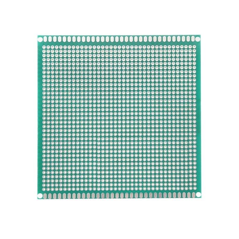
10×10cm Universal PCB Prototype Board
Build your rectifier circuit permanently on this single-sided prototype PCB. 2.54mm pitch holes fit all standard through-hole components perfectly.
Frequently Asked Questions
Q1: Which rectifier circuit type is best for a general-purpose DC power supply?
The bridge rectifier is the best choice for most general-purpose DC power supplies. It offers the same efficiency as a centre-tap full-wave rectifier but does not require a centre-tapped transformer, making it cheaper and more flexible. Ready-made bridge rectifier modules (like the W04 or DB107) are available for just a few rupees in India.
Q2: What is the difference between ripple factor and rectifier efficiency?
The ripple factor measures how much AC remains in the rectified DC output — a lower ripple factor means cleaner DC. Rectifier efficiency measures what percentage of the input AC power is converted into useful DC output power. The half wave rectifier has a high ripple factor (1.21) and low efficiency (40.6%), while bridge and full-wave rectifiers have much better numbers (0.48 ripple, 81.2% efficiency).
Q3: Can I use a rectifier without a transformer?
Yes, but it is dangerous for mains voltage circuits. Transformerless (capacitive dropper) power supplies use a bridge rectifier directly across 230V mains with a capacitive impedance dropper. These are used in some cheap LED drivers and chargers in India but present a serious shock hazard since the output is not isolated from mains. Always use a transformer for isolation in any circuit you will touch.
Q4: Why does a bridge rectifier output less voltage than expected?
A bridge rectifier has two diodes in the current path at any given time, each dropping approximately 0.7V. So the total forward voltage drop is about 1.4V. For a 12V AC RMS transformer (peak ≈ 17V), the peak DC output after the bridge is approximately 17V – 1.4V = 15.6V. After a capacitor filter, your unloaded DC output will be close to 15.6V, not 17V.
Q5: What capacitor value should I use for filtering a bridge rectifier?
The rule of thumb is 1000µF per ampere of load current for a 100 Hz ripple frequency (full-wave rectifier in India at 50 Hz mains). For a 500mA load, use a 470µF to 1000µF capacitor. For 1A, use 1000µF to 2200µF. Always use a capacitor rated at least 50% higher voltage than your peak DC output. For example, for a 12V regulated supply (peak ≈ 17V unregulated), use a 25V or 35V rated capacitor.
Conclusion
Understanding rectifier circuit types — half wave, full wave, and bridge — is fundamental to electronics. The half wave rectifier is the simplest but least efficient; the full wave centre-tap is efficient but needs a special transformer; and the bridge rectifier gives you the best combination of efficiency, cost, and flexibility. Whether you are designing your first power supply on a breadboard or building a professional bench supply, this knowledge will serve you well throughout your electronics journey.
Ready to start building? Zbotic stocks all the passive components, prototype PCBs, and power supply modules you need to put these rectifier circuits into practice. Explore our Electronics Components & Basics collection and start experimenting today!


Add comment