
A potentiometer — affectionately called a “pot” by electronics enthusiasts — is one of the most versatile passive components in any maker’s toolkit. Understanding potentiometer types linear logarithmic and their differences can make or break the feel of a user interface or the accuracy of a sensor circuit. From the volume knob on your speaker to the contrast adjust on an LCD, pots are everywhere. This guide explains the main types, their taper curves, how to wire them, and which type to choose for different Indian maker projects.
How a Potentiometer Works
A potentiometer consists of a resistive element (usually carbon composition, cermet, or conductive plastic) with two end terminals, and a sliding contact called the wiper that taps off a fraction of the total resistance. The wiper position is controlled by rotating a shaft (rotary pot) or sliding a track (slide pot).
This gives you three terminals: terminal 1 (one end of resistor), terminal 2 (other end), and terminal 3 (wiper). By connecting voltage across terminals 1 and 2, you get a variable voltage at terminal 3 — this is the classic voltage divider configuration. If you only use one end terminal and the wiper, you have a variable resistor (technically a rheostat).
Key parameters to note when buying pots in India:
- Resistance value: 100Ω, 1kΩ, 10kΩ, 100kΩ, 1MΩ are most common
- Taper: Linear (B) or Logarithmic (A) — this is the most important and most misunderstood parameter
- Power rating: Typically 0.1W–1W for panel pots
- Shaft diameter and length: 6mm is standard; 3mm for smaller panel cutouts
Linear Taper Potentiometer
A linear taper potentiometer (marked “B” in most Asian/Indian markets, “A” in European standards — confusingly) changes resistance uniformly with shaft rotation. If you rotate the shaft from 0° to 270° (typical travel), the resistance increases by equal amounts for equal angles of rotation. At 135° (exactly halfway), you get exactly 50% of the total resistance.
Resistance vs Rotation Curve
The resistance-rotation graph is a straight diagonal line — hence “linear”. This makes linear pots ideal for applications where you need proportional, predictable control:
- Sensor calibration: Setting precise offset voltages in op-amp circuits
- LED brightness control: Direct brightness appears linear to measurement instruments
- Servo position control: Directly maps angle to a servo position
- Arduino analog input: Reading position as a number (0–1023)
- LCD contrast adjustment: The 10kΩ pot connected to pin 3 of an LCD
Linear pots are the default choice for most electronics projects and are what you almost always get when you buy a generic “10kΩ pot” from a local shop.
Logarithmic (Audio) Taper Potentiometer
A logarithmic taper potentiometer (marked “A” in most Asian/Indian markets) changes resistance following a logarithmic curve. The resistance changes rapidly near the low end and slowly near the high end. At 50% rotation, you typically get only 10–20% of the total resistance.
Why Logarithmic? The Human Ear Explanation
This is brilliant psychoacoustics: human perception of loudness is logarithmic (it follows the decibel scale, which is logarithmic). When you turn a volume knob, you want it to feel like equal steps of loudness increase throughout the rotation — not have most of the audible range crammed into the first 20° of turn.
With a linear pot as a volume control, 50% rotation = 50% voltage = far too loud for normal listening levels; most of the useful range is in the first quarter-turn. With a log pot, 50% rotation = ~10–20% resistance = a comfortable mid-volume, and the full rotation spreads the audible range evenly across the knob travel.
Applications of Logarithmic Taper Pots
- Audio volume controls: Amplifiers, mixers, audio interfaces
- Tone controls: Bass, mid, treble controls on audio equipment
- Motor speed control: Where human perception of motor speed is roughly logarithmic
- Light dimmers: Where perceived brightness follows a power law
| Aspect | Linear (B taper in India) | Logarithmic (A taper in India) |
|---|---|---|
| Resistance curve | Straight line | Curved (log function) |
| At 50% rotation | 50% resistance | ~10–20% resistance |
| Best for | Sensor circuits, Arduino, calibration | Audio volume, tone, human-feel controls |
| Indian marking | B (sometimes “LIN”) | A (sometimes “LOG” or “AUDIO”) |
Trimpots and Trimmer Potentiometers
A trimpot (trimmer potentiometer) is a miniature, PCB-mounted potentiometer intended for one-time or infrequent adjustment during calibration — not for regular user interaction. Unlike panel-mount pots with large shafts and knobs, trimpots are adjusted with a small flathead or Phillips screwdriver.
Types of Trimpots
- Single-turn trimpot: 270° rotation range. Quick to set but less precise. Common footprints: 3362P (vertical), 3386P (horizontal)
- Multi-turn trimpot (cermet): 10–25 turns for very precise setting. Uses a helical resistor track. Often used in precision instruments and DC motor controllers
- Top-adjust vs side-adjust: Top-adjust screws face upward (accessible with PCB installed), side-adjust face sideways (good for front-panel access)
Common Trimpot Applications in Indian Projects
- Setting the threshold on LM393 comparator modules (motor speed, light sensors)
- Adjusting the sensitivity of IR obstacle sensors and PIR sensors
- Calibrating op-amp offset null
- Setting output voltage on adjustable voltage regulators (LM317)
- LCD contrast adjust on 16×2 I2C LCD modules
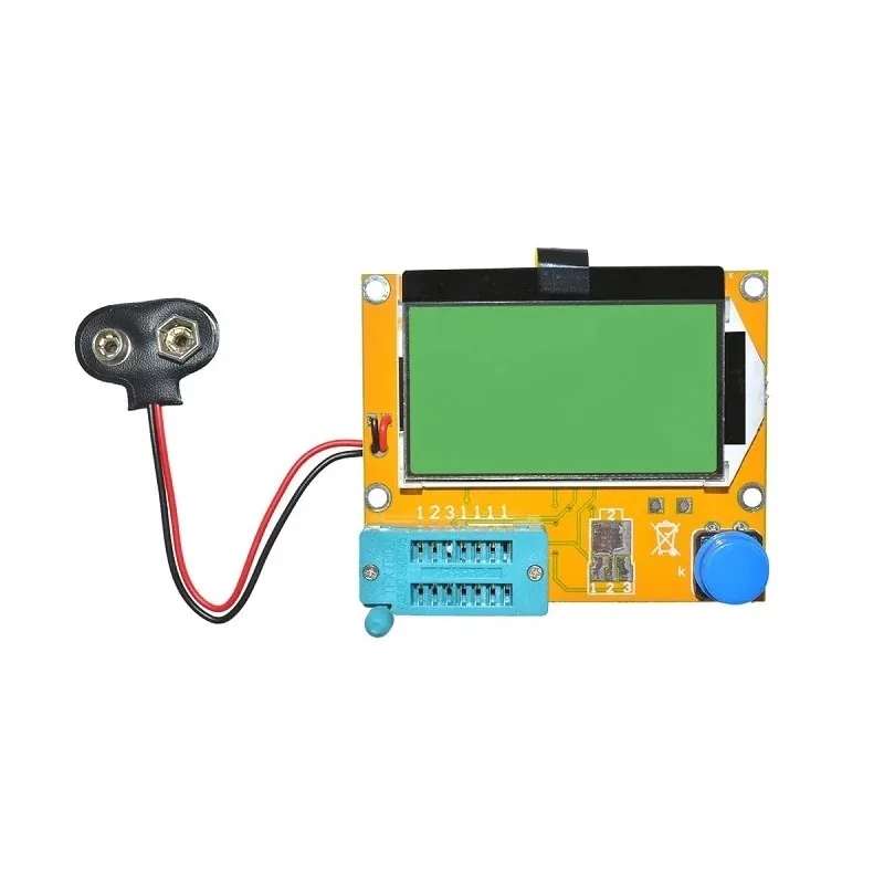
LCR-T4 Graphical Transistor Tester — Resistance, Capacitance, ESR
Test and identify potentiometers, resistors, capacitors, and transistors instantly. Auto-detects component type and displays parameters on the graphical LCD.
Other Types: Slide, Multi-turn, Digital Pot
Slide Potentiometers
Slide pots have a linear (straight-line) travel rather than rotary motion. Common in mixing consoles, graphic equalizers, and lighting dimmers. Available in travel lengths from 10 mm to 100 mm. They can be linear or logarithmic taper. Arduino-compatible slide pots are popular for DIY synthesizer and DJ controller projects.
Multi-turn Rotary Potentiometers
Standard pots have 270°–300° of rotation. Multi-turn pots require 3, 5, or 10 full revolutions from minimum to maximum. This allows extremely fine adjustment and is used in precision instruments, fine frequency tuning, and laboratory equipment.
Digital Potentiometers (DigiPot)
ICs like the MCP4131 (SPI) or DS3502 (I2C) are digital potentiometers — resistor ladder networks controlled by a microcontroller. They allow software-controlled resistance adjustment with no mechanical parts. Used in programmable gain amplifiers, automatic calibration systems, and remote-controlled audio equipment. Prices start around ₹80–₹200 in India.
Wiring a Potentiometer: Voltage Divider and Variable Resistor
Voltage Divider (3-wire) Connection
This is the standard way to use a pot with Arduino or any analog circuit:
- Pin 1 (left end) → VCC (5V or 3.3V)
- Pin 2 (wiper/middle) → Analog input of microcontroller
- Pin 3 (right end) → GND
Output voltage = VCC × (wiper position / max resistance)
Variable Resistor (2-wire / Rheostat) Connection
- Pin 1 (left end) → Circuit input
- Pin 2 (wiper) → Circuit output (or connect pin 2 and pin 3 together to prevent open circuit)
- Pin 3 is left unconnected or tied to pin 2
Important: Never leave pin 3 (the unused end) floating when using as a rheostat — always tie it to the wiper. If the wiper contact becomes intermittent (worn track), a floating end-terminal creates an open circuit which can damage downstream components.

10CM Male To Female Breadboard Jumper Wires 2.54MM – 40Pcs
Connect your potentiometer pins to your Arduino or breadboard with ease. 40 colour-coded wires for clean wiring.
Using a Potentiometer with Arduino
// Potentiometer → Arduino Analog Read
// Wire: Pin1→5V, Pin2(wiper)→A0, Pin3→GND

#define POT_PIN A0
#define LED_PIN 9  // PWM pin

void setup() {
  Serial.begin(9600);
  pinMode(LED_PIN, OUTPUT);
}
void loop() {
  int potValue = analogRead(POT_PIN);  // 0–1023
  int brightness = map(potValue, 0, 1023, 0, 255);
  analogWrite(LED_PIN, brightness);    // Control LED brightness

  float voltage = (potValue / 1023.0) * 5.0;
  Serial.print("ADC: "); Serial.print(potValue);
  Serial.print(" | Voltage: "); Serial.print(voltage, 2);
  Serial.println("V");
  delay(100);
}
Smooth ADC Readings (Anti-jitter)
// Average 8 readings for stable ADC output
int readPotSmooth(int pin) {
  long sum = 0;
  for (int i = 0; i < 8; i++) {
    sum += analogRead(pin);
    delayMicroseconds(100);
  }
  return sum / 8;
}
10×10 cm Universal PCB Prototype Board Single-Sided 2.54mm
Mount your potentiometers and other components permanently on this universal PCB for a clean, professional build.
How to Choose the Right Pot
- For volume control or audio: Always use logarithmic (A taper) 10kΩ or 50kΩ
- For Arduino analog input: Linear (B taper) 10kΩ is the standard
- For calibration (one-time adjust): Use a trimpot — saves panel space and prevents accidental adjustment
- For high-current motor speed control: Use a wirewound pot rated for the required power
- Resistance value guidance: 10kΩ is the most versatile value for microcontroller projects (low enough for stable ADC readings, high enough to not waste significant current)
- For precision circuits: Cermet multi-turn trimpot over single-turn carbon pots
Frequently Asked Questions
Q1: Why does my 10kΩ pot read 12kΩ on my multimeter?
Carbon composition and carbon film pots typically have a ±20% tolerance. A 10kΩ pot reading 8kΩ to 12kΩ is completely normal and within spec. For tight tolerance applications, use 1% cermet trimpots or multi-turn precision pots.
Q2: Can I replace a logarithmic pot with a linear pot in an audio circuit?
Yes, but the volume control will feel unnatural — most of the volume range will be crammed into the first quarter of the knob’s rotation, and the rest will feel like minor adjustments. In a pinch, you can approximate log taper behaviour with a linear pot by adding a resistor from the wiper to the low end terminal (a “fake log” configuration), but a proper log taper pot is the right solution.
Q3: What does the “B” marking mean on Indian potentiometers?
In Japan, and consequently in most Asian electronics markets including India, “B” means Linear taper and “A” means Logarithmic (audio) taper. This is the opposite of the European standard (IEC) where “A” is linear and “B” is logarithmic. Always check with the supplier or datasheet to be sure — this marking confusion has caused many failed audio builds!
Q4: My pot is scratchy or jumpy. How do I fix it?
Scratchy pots (erratic resistance when turned) are caused by oxidation or dirt on the resistive track. First, try applying electronic contact cleaner (DeoxIT or similar) through the shaft opening while rotating the pot back and forth. If that doesn’t work, the track is worn and the pot needs replacement. For future prevention, store unused pots in sealed bags.
Q5: What is the difference between a potentiometer and a rheostat?
A potentiometer uses all three terminals to divide voltage (voltage divider). A rheostat uses only two terminals (one end + wiper) to provide a variable resistance in series with a circuit. Functionally, any pot can be wired as a rheostat, but rheostats designed for high-power current control are physically larger and often wirewound.
Get All Your Components at Zbotic
From potentiometers to prototyping boards — Zbotic is your one-stop shop for quality electronics components, shipped fast across India.


Add comment