
Piezoelectric sensors are one of the most fascinating components in electronics. They convert mechanical stress—vibration, impact, bending—directly into electrical voltage, and can also do the reverse: convert electricity into mechanical motion. This dual nature makes them indispensable for vibration detection, knock sensing, industrial monitoring, and even harvesting ambient energy from movement. Whether you are building a knock-activated Arduino project, a structural health monitoring system, or experimenting with energy harvesting from footsteps, understanding piezoelectric sensors is essential.
This comprehensive guide covers everything from the physics behind the piezoelectric effect to practical wiring diagrams, Arduino code, signal conditioning circuits, and real-world project ideas suited for Indian makers and engineers.
What Is a Piezoelectric Sensor?
A piezoelectric sensor is a transducer that generates an electric charge in response to applied mechanical stress. The word “piezo” comes from the Greek word for “press” or “squeeze.” When you tap, bend, or vibrate a piezoelectric element, it produces a measurable voltage. Conversely, applying voltage causes the material to deform mechanically—this property is used in buzzers and ultrasonic transducers.
In maker and DIY electronics, the most common piezo component is the piezo disc or piezo buzzer element—a thin brass disc with a ceramic layer bonded to it. These cost just a few rupees and are used in everything from greeting card music chips to industrial knock sensors. More advanced versions include PVDF (polyvinylidene fluoride) film sensors used in medical ultrasound and wearables, and stack actuators used in precision positioning systems.
The piezoelectric effect was discovered by brothers Jacques and Pierre Curie in 1880. Today it powers billions of devices globally—from gas igniters in kitchen stoves to accelerometers in your smartphone.
How the Piezoelectric Effect Works
Piezoelectric materials have a crystalline structure with no center of symmetry. Common piezoelectric materials include:
- Quartz (SiO2): Natural, very stable, used in clocks and filters
- PZT (Lead Zirconate Titanate): Synthetic ceramic, high sensitivity, most common in sensors
- PVDF film: Flexible, used in wearables and impact sensors
- BaTiO3 (Barium Titanate): Early synthetic piezoelectric, still used in some transducers
When mechanical stress is applied to these materials, the positive and negative charge centers within the crystal lattice separate, creating an electric dipole. The cumulative effect of millions of these dipoles across the material produces a measurable voltage at the surface electrodes. The voltage is proportional to the force applied, making piezo sensors excellent for measuring dynamic forces, vibrations, and shocks.
Importantly, piezoelectric sensors only respond to changes in force—they cannot measure static (constant) pressure because the charge leaks away through the sensor’s own resistance over time. For static force measurement, you need a load cell or FSR instead.
Types of Piezoelectric Sensors
1. Piezo Disc (Ceramic Buzzer Element)
The most common type in hobbyist projects. A thin brass or stainless steel disc (typically 20–35mm diameter) with a PZT ceramic layer. Generates 1–50V peak from a sharp tap. Dual use: works as a microphone (detects vibration) or a speaker/buzzer (produces sound from voltage). Available for ₹5–₹30 each.
2. PVDF Film Sensor
A flexible piezoelectric film made from PVDF polymer. Can be bent and attached to curved surfaces. Excellent for human motion detection, footstep energy harvesting, and wearable electronics. Generates lower voltages than ceramic but is very sensitive to gentle impacts.
3. Piezoelectric Accelerometer
Used in industrial vibration monitoring and condition monitoring of machinery. Typically mounted on motors, pumps, and bearings to detect abnormal vibrations indicating wear or imbalance. Output is charge (pC/g) or voltage (mV/g). Requires charge amplifiers for signal conditioning.
4. Ultrasonic Piezoelectric Transducer
Operates at frequencies above 20kHz. Used in distance measurement (HC-SR04 uses piezo elements), liquid level sensing, flow measurement, and medical imaging. The transmitter and receiver are separate elements, or a single element alternates between transmit and receive modes.
5. Piezoelectric Force Sensor
Measures dynamic force in manufacturing, testing, and biomechanics. Cylindrical or disc-shaped, can measure forces from millinewtons to meganewtons depending on design. Used in CNC machining (tool force monitoring) and crash testing.
Key Specifications to Know
| Parameter | Typical Value (Piezo Disc) | Significance |
|---|---|---|
| Resonant Frequency | 1–10 kHz | Maximum sensitivity at this frequency |
| Open Circuit Voltage | 10–100V peak (sharp tap) | Must be clamped before ADC input |
| Capacitance | 10–50 nF | Affects frequency response |
| Operating Temperature | -40°C to +85°C | Ceramic Curie temp limits high temp use |
| Diameter | 20–35mm common | Larger = lower resonant frequency |
| Sensitivity | -60 to -40 dB (ref 1V/Pa) | Higher (less negative) = more sensitive |
Wiring a Piezo Sensor to Arduino
Piezo discs generate high voltages (up to 100V open circuit from a sharp tap), far exceeding Arduino’s 5V analog input. You must use a voltage divider and protection diodes before connecting to an analog pin.
Safe Wiring Circuit
Piezo (+) ──┬── 1MΩ resistor ── Arduino A0
            |
           1MΩ to GND  (forms voltage divider)
            |
Piezo (-) ── Arduino GND

Protection: Add two Schottky diodes (1N5819) across A0–GND and A0–VCC
This clamps input to 0–5V range safely.
The 1MΩ resistor to ground serves two purposes: it bleeds off the charge (preventing DC drift) and divides the voltage. With two 1MΩ resistors forming a divider, a 10V piezo pulse appears as 5V at the ADC—right at the limit. Use a smaller bleed resistor (like 470kΩ) for extra safety if you expect hard impacts.
Connection Table
| Piezo Terminal | Circuit | Arduino |
|---|---|---|
| Positive (red wire / top) | 1MΩ to A0, 1MΩ to GND | A0 (via resistor divider) |
| Negative (black wire / chassis) | Direct | GND |
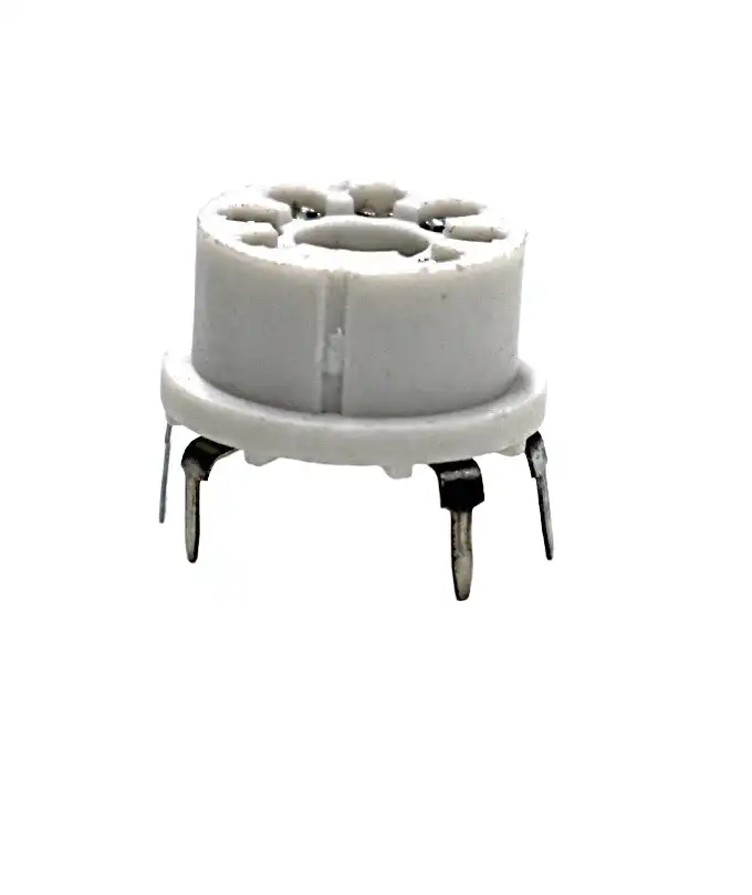
7 Pin Universal Sensor Socket
Useful for securely mounting and prototyping with various sensor modules without soldering directly to your project board.
Arduino Code for Vibration and Knock Detection
Basic Knock/Vibration Detection
const int piezoPin = A0;
const int ledPin = 13;
const int threshold = 100;  // Adjust based on sensitivity needed

void setup() {
  pinMode(ledPin, OUTPUT);
  Serial.begin(9600);
  Serial.println("Piezo Vibration Detector Ready");
}

void loop() {
  int piezoValue = analogRead(piezoPin);

  if (piezoValue > threshold) {
    digitalWrite(ledPin, HIGH);
    Serial.print("Vibration detected! Value: ");
    Serial.println(piezoValue);
    delay(100);  // Debounce
    digitalWrite(ledPin, LOW);
  }
}
Advanced: Knock Pattern Recognition
const int piezoPin = A0;
const int threshold = 150;
const int maxKnocks = 10;
const int knockTimeout = 1500;  // ms to wait for next knock

int knockTimes[maxKnocks];
int knockCount = 0;
unsigned long lastKnockTime = 0;
bool listening = false;

void setup() {
  Serial.begin(9600);
  Serial.println("Knock Pattern Detector");
}

void loop() {
  int piezoValue = analogRead(piezoPin);
  unsigned long now = millis();

  if (piezoValue > threshold) {
    if (knockCount  0 && (now - lastKnockTime > knockTimeout)) {
    Serial.print("Pattern: ");
    Serial.print(knockCount); Serial.println(" knocks");

    // Check for 3-knock pattern (secret knock)
    if (knockCount == 3) {
      Serial.println("SECRET KNOCK RECOGNIZED!");
      // Trigger action here
    }
    knockCount = 0;
  }
}
Vibration Intensity Logger
// Read peak vibration over a sampling window
const int piezoPin = A0;
const int sampleWindow = 50;  // ms

void setup() { Serial.begin(9600); }

void loop() {
  unsigned long startTime = millis();
  int peakValue = 0;
  int minValue = 1023;

  while (millis() - startTime  peakValue) peakValue = val;
    if (val < minValue) minValue = val;
  }

  int peakToPeak = peakValue - minValue;
  // Convert to approximate mV (5000mV / 1024 steps)
  float voltage = peakToPeak * (5000.0 / 1024.0);

  Serial.print("Peak-to-Peak: "); Serial.print(voltage); Serial.println(" mV");
  delay(100);
}
Signal Conditioning Circuits
Raw piezo output is noisy and needs conditioning before it is usable in precision applications.
Charge Amplifier
For accurate measurements, piezo sensors are best connected to a charge amplifier (transimpedance amplifier). An op-amp (LM358, TL071) with a feedback capacitor converts the piezo’s charge output to a stable voltage. The sensitivity is set by the ratio of the feedback capacitor to the piezo capacitance.
Basic charge amplifier:

Piezo (+) ─── op-amp (-) ─── output
                  |______Cf (feedback cap, e.g. 100pF)___|
                  |______Rf (feedback resistor, e.g. 100MΩ)|
Piezo (-) ─── op-amp (+) ─── GND

Sensitivity = -1/Cf  (V per Coulomb)
Envelope Detector
For simple vibration presence detection, a diode-capacitor envelope detector rectifies the AC piezo signal and produces a smoothed DC output proportional to vibration amplitude. Perfect for threshold comparators.
Bandpass Filter
If you are interested only in specific vibration frequencies (e.g., 100–1000Hz for machine monitoring), add a bandpass filter between the piezo and ADC. This rejects low-frequency motion artifacts (hand tremor, thermal drift) and high-frequency electrical noise.
Energy Harvesting with Piezo Elements
Piezoelectric energy harvesting (PEH) converts ambient mechanical energy—footsteps, vehicle vibration, wind-induced flutter—into usable electrical energy. While the power levels are modest (microwatts to milliwatts), advances in ultra-low-power microcontrollers make this viable for wireless sensor nodes.
How Much Energy Can You Harvest?
A typical 35mm piezo disc harvesting from footstep vibration generates approximately 50–200 microwatts average power. A stack of 10 discs in parallel under a floor tile might generate 1–5 mW per step. This is sufficient to power a temperature sensor transmission every few minutes using an ultra-low-power MCU like the ATtiny85 or TI MSP430.
Energy Harvesting Circuit
The harvested AC signal must be rectified and regulated:
- Full-wave bridge rectifier: Use Schottky diodes (e.g. 1N5819) for minimal forward voltage drop (0.3V vs 0.7V for silicon)
- Storage capacitor: Large electrolytic (100–1000μF) to smooth the rectified output
- LTC3588 or BQ25504: Dedicated piezo energy harvester ICs with MPPT and boost converter
- Supercapacitor: 1F–10F for longer energy storage, better for intermittent loads
Piezo ─── Full-wave bridge (1N5819) ─── 470μF cap ─── LTC3588-1 ─── 3.3V regulated output
                                                              |
                                                        Supercapacitor (1F)
Improving Harvested Power
- Impedance matching: Maximum power transfer when source and load impedance match. Piezo source impedance is capacitive (10–50nF), so an inductance-based impedance matching network can double extracted power.
- Mechanical resonance: Design the cantilever beam holding the piezo to resonate at the dominant vibration frequency (e.g. 50Hz from mains-frequency machine vibration)
- PVDF film: More flexible, better for low-frequency bending applications
- Series vs parallel stacking: Multiple discs in series increase voltage; in parallel increase current. Match to your regulator’s input requirements.

10Kg Load Cell – Electronic Weighing Scale Sensor
When you need static force measurement (piezo cannot do this), a load cell with HX711 amplifier is the right choice for weighing applications.
Real-World Applications
1. Structural Health Monitoring (SHM)
Piezoelectric sensors are permanently embedded in bridges, buildings, and aircraft structures to continuously monitor for cracks, fatigue, and delamination. Lamb wave techniques use piezo actuators to send ultrasonic waves through structures; sensors at other points detect changes in wave patterns indicating damage.
2. Industrial Machine Condition Monitoring
Piezoelectric accelerometers mounted on motor bearings detect the characteristic frequency signatures of bearing wear, imbalance, and misalignment long before catastrophic failure. This enables predictive maintenance, saving lakhs of rupees in downtime costs for Indian manufacturing plants.
3. Musical Pickup Systems
Acoustic guitar pickups often use piezo elements under the saddle to detect string vibrations. Piezo pickups are also used in sitars, tablas, and other Indian classical instruments for live amplification without altering the acoustic characteristics.
4. Ignition Systems
Gas stove igniters, cigarette lighters, and BBQ lighters use piezoelectric strikers. A spring-loaded hammer strikes a PZT crystal, generating a high-voltage (>10kV) spark. No battery required—purely mechanical-to-electrical conversion.
5. Medical Ultrasound
Diagnostic ultrasound machines use arrays of piezoelectric transducers to transmit and receive high-frequency (1–20MHz) sound waves through tissue. The time-of-flight and reflection characteristics create detailed images of organs and blood flow.
6. Smart Floor Energy Harvesting
Airports and railway stations in Japan and Europe use piezo tiles under high-traffic areas to generate supplemental electricity. Each footstep generates a small pulse; millions of steps per day add up to meaningful energy. India’s busy railway stations could benefit enormously from this technology.
7. Knock Sensor for Engine Management
Modern petrol engines use piezoelectric knock sensors mounted on the engine block to detect detonation (knocking/pinking). The ECU retards ignition timing when knock is detected, preventing engine damage while maximising efficiency.

BMP280 Barometric Pressure and Altitude Sensor
Complement your vibration sensing projects with environmental monitoring—pressure and altitude sensing for complete IoT data logging systems.
Practical Tips and Common Mistakes
Tips for Better Results
- Mount firmly but not rigidly: The piezo disc needs to flex to generate voltage. Clamping the entire disc prevents vibration. Mount only the rim, leaving the center free to flex.
- Use a 1MΩ bleed resistor: Always connect a 1MΩ resistor from the piezo positive terminal to ground. Without it, static charge accumulates and saturates your ADC.
- Shield the wires: Piezo sensors are sensitive to electromagnetic interference. Use shielded cable (coaxial or twisted pair with shield) for runs longer than 30cm.
- Epoxy for permanent mounting: For outdoor or industrial use, apply a thin layer of silicone or epoxy to seal the ceramic layer from moisture. Water on the ceramic layer causes leakage and erratic readings.
- Temperature effects: Piezo sensitivity changes with temperature. PZT ceramics can depole (lose piezoelectric properties) above their Curie temperature (~150–350°C depending on grade). Keep below 100°C for reliable operation.
Common Mistakes to Avoid
- No voltage protection: Connecting piezo directly to Arduino ADC without clamping diodes risks destroying the microcontroller with a high-voltage spike from a sharp tap.
- Floating ground: The negative terminal of the piezo must connect to Arduino ground. Floating input causes random readings.
- Expecting DC output: Piezo sensors produce AC (bidirectional) pulses. The ADC reads only positive voltages. Use a half-supply bias (2.5V reference) if you need to capture both polarities.
- Using for static force: Piezo cannot measure constant pressure. The charge dissipates within milliseconds. Use a load cell or FSR for static/quasi-static force measurement.
- Wrong threshold: Setting the threshold too low causes false triggers from ambient vibration. Start high and reduce until you get reliable detection.
Frequently Asked Questions
Yes! A standard piezo buzzer element (the disc without the driving circuit) works as a vibration sensor. Remove the electronic driving circuit if present, and connect only the two wires from the disc itself. The buzzer housing may dampen sensitivity slightly compared to a bare disc.
A piezoelectric sensor converts vibration/force into electrical voltage (sensing). A vibration motor converts electrical energy into mechanical vibration (actuation). They are opposite in function, though piezoelectric elements can do both (using the reverse piezoelectric effect).
Open-circuit voltage from a sharp finger tap on a 27mm disc can be 20–100V peak. However, the available current is extremely small (the disc capacitance is only 10–50nF). The sustained power is microwatts. Always use voltage clamping before connecting to any microcontroller.
A standard Arduino Uno draws 50mA at 5V (250mW) — far more than practical piezo harvesting. However, an ATtiny85 in sleep mode draws only 6μA, waking briefly to transmit sensor data. This can realistically be powered by piezo harvesting from regular footstep vibration using energy storage capacitors or supercapacitors.
Piezoelectric ceramic elements are extremely durable with no moving parts. Industrial piezo sensors are rated for billions of cycles. The main failure modes are mechanical cracking from excessive bending, moisture ingress into the ceramic layer, and thermal depolarisation above the Curie temperature.
A piezoelectric accelerometer is a type of accelerometer that uses the piezoelectric effect, but MEMS accelerometers (like the ADXL345 or MPU-6050 used with Arduino) use a different principle—capacitive sensing. MEMS accelerometers can measure DC (static) acceleration including gravity, while piezo accelerometers only measure dynamic (changing) acceleration.
Conclusion
Piezoelectric sensors are among the most versatile transducers available to electronics makers. From the humble ₹10 piezo disc in your Arduino starter kit to precision industrial accelerometers costing thousands, the fundamental physics—mechanical stress creating electrical charge—remains the same. The key to using them successfully lies in proper signal conditioning (voltage clamping, bleed resistors, charge amplifiers), understanding their AC-only output nature, and matching the sensor type to your application.
Whether you are building a knock-activated secret door, monitoring machine vibrations for predictive maintenance, or harvesting energy from ambient mechanical sources, piezoelectric sensors offer a unique and elegant solution. Experiment with different mounting configurations, thresholds, and signal processing techniques to unlock their full potential in your next project.
Ready to Start Your Piezo Project?
Explore Zbotic’s full range of sensors and measurement modules for your next electronics project.


Add comment