
One of the most underrated steps in DIY electronics is the drilling of through-holes in a custom PCB. Use a handheld rotary tool freehand and you’ll quickly discover how easy it is to snap a 0.8mm drill bit, wander off-centre, or crack the PCB substrate. A dedicated PCB drill machine or micro drill press solves all of these problems by providing controlled depth, perfectly vertical drilling, and the high RPM required to cut cleanly through fibreglass without shattering tiny bits.
This guide covers everything Indian hobbyists and makers need to know about selecting and using the right PCB drilling setup — from standalone micro drill presses to PCB drill stations that convert your rotary tool into a precision press.
Why a Dedicated PCB Drill Matters
FR4 PCB material (the standard fibreglass epoxy substrate) is abrasive and hard. The drill holes required are tiny — typically 0.6mm to 1.2mm for component leads and vias. This combination creates a demanding set of requirements:
- High RPM: PCB drilling requires 20,000–35,000 RPM for clean cuts. Standard power drills operate at 1,000–3,000 RPM — far too slow, which causes fibreglass delamination and bit breakage.
- Perpendicular axis: Even a 2° tilt on a 0.8mm bit causes it to snap the moment it catches on the fibreglass weave. A drill press column ensures 90° drill entry every time.
- Controlled feed rate: Pressing too hard or too fast snaps bits. A spring-loaded drill press mechanism provides consistent, gentle feed.
- Consistent depth: For double-sided boards, drilling all the way through but not gouging your work surface requires depth stop control.
Even if you only make PCBs occasionally, a micro drill press is one investment that pays for itself in saved drill bits alone.
Types of PCB Drill Machines
Standalone Micro Drill Press / PCB Drill Station
This is the most purpose-built solution. It’s a dedicated bench-top unit with a column, a spring-loaded arm, a chuck, and its own DC or AC motor running at high RPM. Good standalone units run at 7,000–35,000 RPM with variable speed control. They typically include a base with a sacrificial board slot, a depth stop ring, and a PCB stage.
Pros: purpose-designed, no adapter needed, often quieter than rotary tools
Cons: larger footprint, higher cost
Drill Press Stand for Rotary Tools (Drill Station)
This is the most popular choice for Indian hobbyists. A drill press stand accepts a standard rotary tool (like a Dremel, ProCraft, or similar) and turns it into a drill press. The stand provides the column, spring arm, and depth stop, while the rotary tool provides the motor and chuck. These are compact, affordable, and versatile since the rotary tool can be removed for handheld use.
Pros: affordable, compact, versatile, widely available
Cons: alignment depends on the fit between stand and tool
PCB Hand Drill / Pin Vice
For occasional use on soft PCB materials or thin single-sided boards, a pin vice (a precision hand chuck) with carbide drill bits can work. This is the slowest and most fatiguing option but the cheapest. Not recommended for FR4 in significant quantities.
CNC PCB Routers
At the high end, desktop CNC machines with a spindle can drill and route PCBs under computer control. Products like the Genmitsu 3018 or similar accept 0.8–3.175mm end mills and drill bits. This is overkill for most hobbyists but excellent for production of small PCB runs.
Understanding PCB Drill Bits
Standard HSS (High-Speed Steel) drill bits are inadequate for FR4. The fibreglass weave dulls them within a few holes. PCB-grade carbide drill bits are what you need.
Carbide vs. HSS Drill Bits
| Property | Carbide PCB Bits | HSS Bits |
|---|---|---|
| Hardness | Very high (HRA 89–93) | Moderate (HRC 62–66) |
| FR4 Lifespan | 1,000–3,000 holes/bit | 10–30 holes/bit |
| Brittleness | High — snaps if tilted | More flexible |
| Cost | Higher per bit | Lower per bit |
| Best For | FR4, multilayer PCBs | Soft boards, phenolic |
Common PCB Drill Bit Sizes
- 0.6mm: Vias, fine-pitch through-hole pads
- 0.8mm: Standard IC through-hole, capacitor leads, resistor leads
- 1.0mm: General component leads, pin headers
- 1.2mm: Thicker leads, mounting pads for 3.5mm connectors
- 3.175mm (1/8 inch): Mounting holes for standoffs
Most projects need 0.8mm and 1.0mm bits most heavily. Buy spares — they do snap.
Key Specifications to Compare
When evaluating a PCB drill machine or drill press stand, compare these specifications:
Speed (RPM)
Higher RPM produces cleaner cuts in FR4. Look for at least 15,000 RPM for PCB work. Variable speed is useful since softer materials (acrylic, thin phenolic) prefer lower speeds to avoid melting.
Chuck Size
PCB drill bits have shank diameters of 0.3mm to 3.175mm. The chuck must accommodate this range. Most micro drill presses use a 0.3–3.2mm or 0.5–3.5mm collet-type chuck. Check that very fine bits (0.6mm) won’t wobble in the chuck.
Column Height and Travel
The column must be tall enough for your workpiece plus a bit holder. Vertical drill travel (stroke) of 30–50mm is adequate for PCBs up to 5mm thick (including sacrificial board).
Depth Stop
An adjustable depth stop ring lets you set a consistent drill-through depth. This prevents drilling into your work surface repeatedly and wearing out the tip of the bit.
Table/Base Area
The base needs to comfortably hold a 10×10cm PCB or larger. Some drill presses have cross-slide tables for X/Y positioning — useful but not essential for hobby use.
Recommended Products from Zbotic
While dedicated PCB drill presses are best purchased from local electronics markets or specialty tool suppliers, Zbotic offers the essential PCB supplies you’ll be drilling into. These are the prototype boards most commonly used with micro drill presses:

10 x 10 cm Universal PCB Prototype Board Single-Sided 2.54mm Hole Pitch
Standard 10×10cm FR4 single-sided prototype board with 2.54mm hole pitch. The most common substrate for hobby drilling and hand-wired circuit assembly. Quality board that drills cleanly with the right bit.
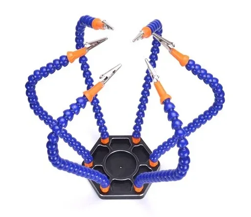
6 Flexible Arms Soldering Station With Swiveling Alligator Clip
After drilling, this helping hands station holds your PCB securely for soldering. Six flexible gooseneck arms with alligator clips give you multiple hold points and a magnifier — perfect companion to a PCB drill press workflow.

BAKON Soldering Iron Tip 900M-T-I
Once your PCB is drilled, you’ll need a sharp, reliable soldering tip to populate it. The BAKON 900M-T-I tip (I-shape, chisel-point) is excellent for through-hole component soldering on prototype boards.

0.1MM Copper Enamelled Repair Reel Wire
Fine enamelled copper wire for routing signals between drilled through-holes on single-sided boards. Indispensable for jumper wiring when you can’t route traces to avoid crossings on a single-layer board.
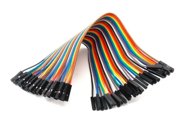
10CM Female To Female Breadboard Jumper Wires – 40Pcs
Prototype your circuit on a breadboard first before committing to a drilled PCB. These 40-piece female-to-female jumper wire packs let you test your design with Arduino/Raspberry Pi quickly before moving to board fabrication.
PCB Drilling Technique
Before You Drill
- Print and align your drill template. Print your PCB layout at 1:1 scale, tape it to the copper-clad or etched board, and centre-punch each hole lightly with a sharp pick or automatic centre punch. This prevents the bit from wandering when it first contacts the board.
- Set your depth stop. Place a sacrificial board (a piece of scrap PCB or MDF) under your workpiece. Set the depth stop so the bit exits 1–2mm into the sacrificial board. This ensures clean exit holes.
- Check RPM. For 0.8mm carbide bits, run at maximum RPM (25,000–35,000). For 3mm bits, reduce to 15,000–20,000 to prevent overheating.
During Drilling
- Apply steady, gentle downward pressure. Let the speed do the work — do not force the bit.
- Withdraw the bit every 5–10mm to clear fibreglass dust from the flutes. This is called “pecking” and dramatically extends bit life.
- Wear eye protection and a dust mask — fibreglass dust is a respiratory irritant.
- Drill the smallest diameter holes first (0.6mm vias), then progress to larger holes. The larger holes may need a slight widening of your template punch marks.
After Drilling
- Deburr holes with a slightly larger bit turned by hand (no power), or use a dedicated deburring tool.
- Blow out dust with compressed air or a bulb blower before soldering.
- Inspect under magnification — misaligned or delaminated holes need to be noted on the schematic for any required design revision.
Troubleshooting Common Problems
Drill Bit Keeps Snapping
Causes: too much side pressure, drilling at too low an RPM, bit wobble in chuck, or entering at an angle. Solution: check that the chuck is tight, verify perpendicular setup, reduce feed pressure, and increase RPM. For very fine bits (0.6mm), the entire drill motion should take less than 3 seconds.
Holes Are Oval Instead of Round
The bit is wobbling — either the chuck isn’t gripping properly, the collet is worn, or the bit shank is damaged. Inspect the bit under magnification, clean and re-seat it in the chuck.
Delamination Around the Hole
The feed rate is too high (pressing too hard) or the RPM is too low. The fibreglass weave is tearing instead of cutting. Increase RPM, decrease feed pressure, and ensure you are using a carbide bit, not HSS.
Bit Doesn’t Reach All the Way Through
The depth stop is set too shallow, or the board is thicker than expected. Standard PCBs are 1.6mm thick; some are 0.8mm or 2.4mm. Adjust depth stop accordingly.
Frequently Asked Questions
What RPM is needed for drilling PCBs?
PCB drilling typically requires 20,000–35,000 RPM for small bits (0.6–1.2mm). Standard home drills operating at 1,000–3,000 RPM are far too slow, causing fibreglass delamination and rapid bit wear. Use a dedicated PCB drill press or a high-speed rotary tool in a drill press stand.
Can I use a Dremel as a PCB drill?
Yes — a Dremel or similar rotary tool operating at 25,000–35,000 RPM works well for PCB drilling when mounted in a drill press stand. Freehand use is not recommended for fine bits; even a small tilt will snap a 0.8mm carbide bit instantly. Always use the rotary tool in a press stand for PCB work.
What size drill bit is used for standard through-hole components?
The most commonly used size is 0.8mm, which fits resistor leads, capacitor leads, and IC DIP package pins. For larger components like power connectors, inductors, and electrolytic capacitors, 1.0–1.2mm is used. Mounting holes for M3 standoffs require 3.2mm.
How many holes can a carbide PCB drill bit last before needing replacement?
A quality carbide PCB drill bit typically lasts 1,000–3,000 holes in FR4 material at correct speed and feed rate. Bits used at incorrect RPM or with excessive pressure may last as few as 50 holes before snapping or becoming dull. Dull bits produce ragged holes and should be replaced, not sharpened (carbide micro-bits are not economically re-sharpenable).
Is a CNC router better than a micro drill press for PCB making?
A CNC router is more capable — it can drill, mill traces, and cut board outlines under computer control — but is also far more expensive and complex to set up. For a hobbyist making occasional one-off boards, a micro drill press gives 90% of the result at 10% of the cost. CNC makes sense when you are producing multiple identical boards or need precise trace milling.
Shop Zbotic’s range of PCB prototype boards, soldering tools, and electronics components — everything you need from drilling to final assembly, delivered fast across India.


Add comment