
When two circuits operate at different voltage levels, share different grounds, or when you need to protect a sensitive microcontroller from a high-voltage power circuit, the optocoupler is the ideal solution. The PC817 is the most widely used optocoupler (also called optoisolator) in hobbyist and industrial electronics — cheap, reliable, easy to use, and available at virtually every electronics shop in India. This tutorial walks you through exactly how the PC817 works, its complete pinout, how to calculate the correct resistor values, and how to use it in practical circuits including relay drivers, AC mains sensing, and microcontroller input protection.
What Is an Optocoupler?
An optocoupler is a semiconductor device that transfers an electrical signal between two electrically isolated circuits using light. Inside the device, an LED on the input side emits infrared light when current flows through it. A phototransistor on the output side detects this light and allows current to flow in the output circuit proportionally. Because the coupling medium is light (photons), there is no direct electrical connection between input and output — they share no common ground and the voltage on one side cannot damage the other side.
This galvanic isolation is the core value proposition of optocouplers. They are used to:
- Protect 3.3V/5V microcontrollers from 12V, 24V, or 230V AC circuits
- Eliminate ground loops in audio, industrial, and measurement equipment
- Interface microcontrollers to relay coils and motor drivers
- Detect AC mains zero-crossing for TRIAC/thyristor dimmer circuits
- Transmit signals across switching power supply isolation barriers
- Provide noise immunity in industrial automation and PLC systems
PC817 Overview and Specifications
The PC817 (also marketed as EL817, LTV817, SFH617) is a single-channel, general-purpose optocoupler manufactured by Sharp Corporation and widely sourced from Asian manufacturers. It is packaged in a 4-pin DIP (Dual Inline Package), making it breadboard-compatible and ideal for through-hole PCB assembly.
Key Specifications:
- Isolation voltage: 5,000 V AC (RMS) between input and output
- Input LED forward voltage: V_F = 1.2 V (typ.), 1.4 V (max)
- Input LED forward current: I_F max = 50 mA (continuous), recommended 5–20 mA
- Collector-emitter voltage: V_CE max = 35 V
- Collector current: I_C max = 50 mA
- Current Transfer Ratio (CTR): 50–600% at I_F = 5 mA (grade-dependent)
- Response time: Rise/fall time ~4 µs at I_C = 2 mA, R_L = 1 kΩ
- Operating temperature: −30°C to +100°C
- Package: DIP-4, 7.62 mm lead spacing
The CTR varies by grade: PC817A (50–150%), PC817B (100–300%), PC817C (200–600%), PC817D (300–600%). When sourcing from local markets in India, you may receive any grade — always verify CTR if your design is current-sensitive.
PC817 Pinout and Package
The PC817 has 4 pins arranged as follows (pin 1 indicated by a notch or dot on the package):
- Pin 1 — Anode (A): LED input, positive terminal. Connect through resistor to signal source.
- Pin 2 — Cathode (K): LED input, negative terminal. Connect to GND of input circuit.
- Pin 3 — Emitter (E): Phototransistor output, emitter terminal. Connect to output GND.
- Pin 4 — Collector (C): Phototransistor output, collector terminal. Connect to output Vcc through pull-up resistor.
Pins 1–2 belong to the input side (LED). Pins 3–4 belong to the output side (phototransistor). The creepage distance between the two sides is the physical basis for the 5kV isolation rating.
Orientation: When the package is held with the flat side facing you and the notch to the left, Pin 1 is bottom-left, Pin 2 is bottom-right, Pin 3 is top-right (emitter), and Pin 4 is top-left (collector). Always verify with a datasheet for your specific manufacturer.
How the PC817 Works Internally
Inside the PC817 package, an infrared LED and an NPN phototransistor are optically coupled in a small cavity with a transparent medium. The cavity is sealed and opaque to external light, ensuring only the internal LED triggers the phototransistor.
Input side operation: When a voltage is applied across pins 1 and 2 (Anode to Cathode) through a series resistor, current flows through the infrared LED. The LED emits near-infrared light (wavelength ~940 nm) proportional to the current. The LED forward voltage is ~1.2 V, similar to a standard silicon diode.
Output side operation: The infrared photons strike the base region of the NPN phototransistor, generating electron-hole pairs and triggering transistor action. The phototransistor’s collector-emitter current becomes proportional to the light intensity (and therefore proportional to the LED current). The output behaves like a standard NPN transistor but is controlled by light rather than a base pin (the base pin is not externally accessible in most configurations).
Key insight: The PC817 is a passive device — it has no internal power supply. The output current comes from the external output circuit’s power supply (Vcc_out), not from the input. This means input and output circuits can operate at completely different voltage levels with separate grounds.
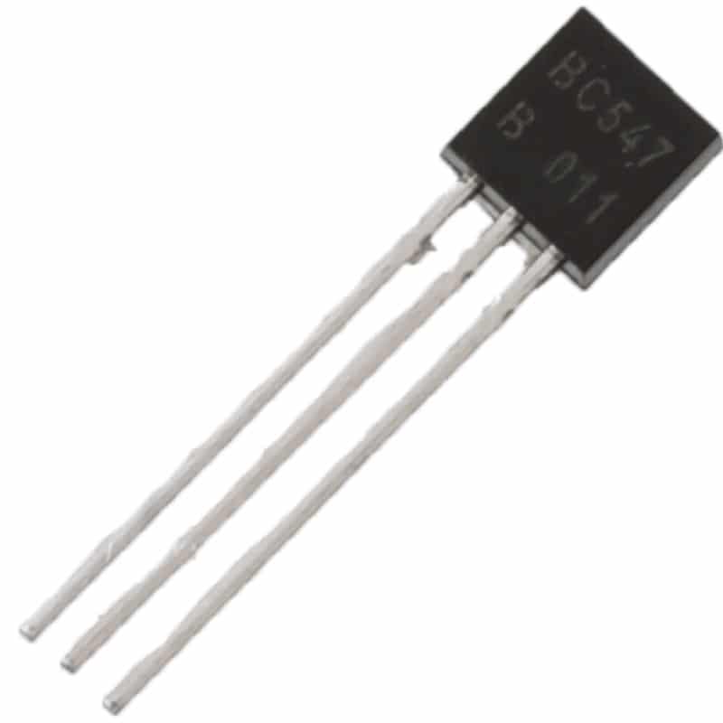
BC547 NPN 100mA Transistor TO-92 (Pack of 10)
Use BC547 transistors alongside PC817 optocouplers to drive relay coils and higher-current loads that exceed the optocoupler’s 50mA collector rating.
Current Transfer Ratio (CTR) Explained
The Current Transfer Ratio is the most important specification for understanding PC817 output capability:
CTR (%) = (I_C / I_F) × 100
Where I_C is the output collector current and I_F is the input LED current. A CTR of 100% means if you inject 10 mA into the LED, you can get up to 10 mA from the collector (given sufficient V_CE and pull-up). A CTR of 200% means 10 mA in allows up to 20 mA out.
However, CTR is only valid when the transistor is in active region (not saturated). In digital switching applications, you typically drive the input with enough current to saturate the transistor (ensure V_CE_sat is low). For reliable saturation:
I_F_required = I_C_load / (CTR_min / 100)
Example: Output pull-up circuit draws I_C = 5 mA, PC817 grade A (CTR min 50%): I_F = 5 / 0.50 = 10 mA minimum input current. Add 2× safety margin → 20 mA for reliable switching.
CTR degrades with temperature and over the device’s lifetime, so always use the minimum CTR value from the datasheet and add margin in your designs.
Resistor Calculation for Input and Output
Input Resistor (R_in)
The input resistor limits current through the LED to the desired I_F.
R_in = (V_in − V_F) / I_F
Where V_in is your input signal voltage, V_F ≈ 1.2 V is the LED forward voltage.
For 5V input, I_F = 10 mA: R_in = (5 − 1.2) / 0.010 = 380 Ω → use 390 Ω standard value
For 3.3V input, I_F = 5 mA: R_in = (3.3 − 1.2) / 0.005 = 420 Ω → use 470 Ω
For 12V input, I_F = 10 mA: R_in = (12 − 1.2) / 0.010 = 1080 Ω → use 1 kΩ
For 24V input, I_F = 10 mA: R_in = (24 − 1.2) / 0.010 = 2280 Ω → use 2.2 kΩ
Output Pull-Up Resistor (R_out)
On the output side, the phototransistor typically drives a pull-up resistor to Vcc_out. The collector pulls low when the LED is ON.
R_out = (V_cc_out − V_CE_sat) / I_C_desired
V_CE_sat ≈ 0.1 V (saturated transistor)
For Vcc_out = 5V, I_C = 5 mA: R_out = (5 − 0.1) / 0.005 = 980 Ω → use 1 kΩ
For Vcc_out = 3.3V, I_C = 3 mA: R_out = (3.3 − 0.1) / 0.003 = 1067 Ω → use 1 kΩ
Digital Signal Isolation Circuit
The most basic PC817 application is isolating a digital signal from one circuit to another. For example, transmitting a 5V logic signal from an Arduino to a 12V industrial PLC input, or vice versa:
INPUT SIDE (5V Arduino):
  Arduino Pin D2 → 390Ω → PC817 Pin 1 (Anode)
  PC817 Pin 2 (Cathode) → Arduino GND

OUTPUT SIDE (12V PLC/Logic):
  12V Supply → 1.2kΩ → PC817 Pin 4 (Collector) → [Output signal point]
  PC817 Pin 3 (Emitter) → 12V GND

Behavior:
  Arduino HIGH (5V) → LED ON → Transistor ON → Collector LOW (~0V)
  Arduino LOW (0V)  → LED OFF → Transistor OFF → Collector HIGH (12V)
  Output is inverted relative to input.
To restore non-inverted logic, add a second logic inversion stage (another NPN transistor, a NOT gate, or invert in software). The output level (12V in this example) is set by the output pull-up supply — completely independent of the 5V input side.
Relay Driver with PC817 and Arduino
A very common Arduino project: switching a 230V AC appliance (fan, light) using a 5V microcontroller. The PC817 provides the isolation barrier between the Arduino and the relay coil circuit:
COMPLETE RELAY DRIVER CIRCUIT:

ARDUINO SIDE:
  D8 → 470Ω → PC817 Pin1 (A)
  PC817 Pin2 (K) → Arduino GND

RELAY SIDE (12V):
  12V → 1kΩ → PC817 Pin4 (C) → BC547 Base → GND
  BC547 Collector → Relay Coil → 12V
  BC547 Emitter → GND
  1N4007 Flyback diode across relay coil (Cathode to 12V, Anode to Collector)

Behavior:
  D8 HIGH → PC817 ON → BC547 Base sees ~4V via 1kΩ → BC547 ON
  → Relay coil energised → Relay contacts close → 230V appliance ON
The BC547 is needed because the relay coil typically draws 50–100 mA — exceeding the PC817’s 50 mA collector rating. The PC817 drives the BC547 base, and BC547 drives the relay. The flyback diode (1N4007) protects the BC547 from the relay coil’s inductive kick when it de-energises.
This circuit gives full galvanic isolation: if a fault occurs in the 230V mains side, the Arduino remains protected by the 5kV isolation barrier inside the PC817.
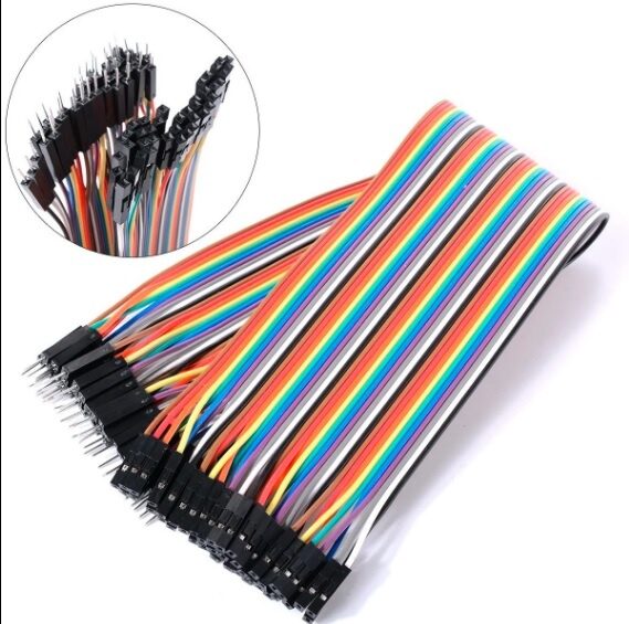
10CM Male To Female Breadboard Jumper Wires 2.54MM – 40Pcs
Connect your Arduino to optocoupler circuits on a breadboard quickly and safely with these 40-piece male-to-female jumper wires.
AC Mains Zero-Cross Detection
TRIAC dimmer circuits and phase-angle controllers must know when the AC mains voltage crosses zero. The PC817 is the standard component for building a safe, isolated zero-cross detector for Indian 230V/50Hz mains:
AC ZERO-CROSS DETECTOR (230V/50Hz):

AC INPUT SIDE:
  L (Live) → 33kΩ (2W) → 33kΩ (2W) → PC817 Pin1 (A)
  PC817 Pin2 (K) → 1N4007 → N (Neutral)
  [Two 33kΩ resistors in series = 66kΩ total for current limiting]
  [Diode allows only positive half-cycle to flow through LED]

MICROCONTROLLER SIDE (5V):
  5V → 10kΩ → PC817 Pin4 (C) → MCU interrupt pin
  PC817 Pin3 (E) → MCU GND

Operation:
  Every 10ms (at 50Hz), AC crosses zero
  LED turns OFF at zero crossing
  Collector goes HIGH → triggers MCU interrupt
  MCU fires TRIAC at precise delay after zero-cross
The two 33kΩ resistors in series limit peak current: at 230V peak (325V), I = 325/66000 ≈ 4.9 mA — within safe LED current limits. Use 2W rated resistors as they will dissipate significant heat from the AC half cycle. This circuit is commonly used in Indian light dimmers, fan speed controllers, and induction cooktop controllers.
Speed, Bandwidth and Rise Time
The PC817 has a relatively slow response time compared to dedicated high-speed optocouplers. Rise and fall time at I_C = 2 mA with 1 kΩ load: approximately 4 µs. This gives a maximum signal frequency of approximately 80–100 kHz before significant signal distortion occurs.
For applications up to 10 kHz (audio isolation, UART at 9600 baud, slow control signals, 50Hz zero-cross), the PC817 is more than adequate. For higher-speed applications such as SPI, CAN bus isolation, or high-speed digital signals, use dedicated high-speed optocouplers like:
- 6N137: Up to 10 Mbps, TTL-compatible output
- HCPL-0302: 15 Mbps for gate driver applications
- IL300: Linear optocoupler for analog signal isolation
- ACPL-C87x series: For isolated ADC and current sensing in power inverters
If you need to increase the PC817’s speed in your circuit, reduce the output pull-up resistor value (increases collector current, speeds up transition) and add a small capacitor (100 pF) from collector to emitter to stabilise the output. Typical improvement: rise time reduced from 4 µs to ~1 µs with 330 Ω pull-up at 5V.
PC817 Alternatives and Upgrades
- EL817 / LTV817: Pin-compatible replacements with identical specs; widely available in India
- PC823: 4-channel version (quad optocoupler) in DIP-16 package — compact for multi-channel designs
- MOC3021/MOC3041: Triac driver optocouplers with built-in zero-cross detection, for directly firing TRIACs from a microcontroller
- 4N35: Similar general-purpose optocoupler but with exposed base pin for speed enhancement
- TLP785: Higher CTR (300–1500%) version for driving more output current with less input drive
- ADUM1201 (iCoupler): Digital isolator using capacitive coupling — faster (1 Mbps+), no LED degradation, but higher cost
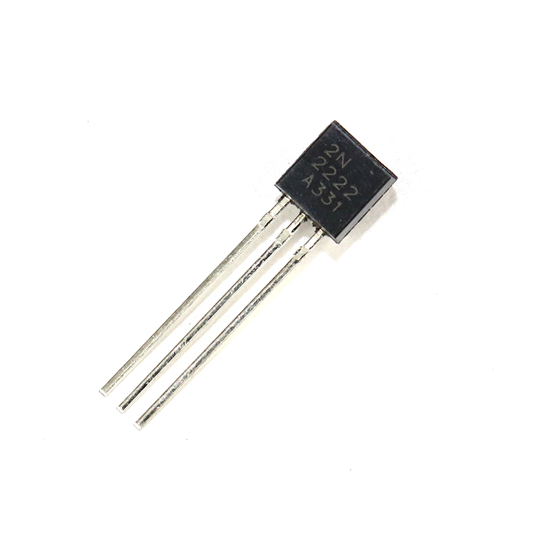
2N2222 NPN Transistor (Pack of 20)
The 2N2222 is an excellent driver transistor to pair with PC817 for relay and solenoid control — rated 600mA, faster switching than BC547, and widely used in isolation circuits.
Frequently Asked Questions
Q1: Can I use the PC817 to isolate a 3.3V ESP32 from a 5V sensor output?
Yes. Connect the 5V sensor output through a 390Ω resistor to PC817 pin 1, pin 2 to sensor GND, pin 4 through a 3.3kΩ pull-up to ESP32’s 3.3V rail, and pin 3 to ESP32 GND. When the sensor goes HIGH (5V), the ESP32 sees LOW (since the transistor pulls its pin to GND). You get level shifting and isolation in one component.
Q2: My PC817 output is not fully switching LOW. What’s wrong?
This usually means insufficient LED current (I_F too low) for the transistor to saturate with your load. Calculate required I_F = I_C / (CTR_min/100) and adjust R_in accordingly. Also verify your PC817 grade — a grade A (CTR min 50%) needs twice the LED current as a grade C (CTR min 200%) for the same output current.
Q3: Why does the output of PC817 become HIGH when LED is ON?
That is the correct behaviour if you are reading the voltage at the pull-up resistor rather than the collector directly. The transistor is ON → collector is LOW, but if your multimeter or MCU pin is measuring at the resistor’s top (Vcc side), that point is always HIGH. Measure at the collector (the junction between the resistor and pin 4). In code, you should see LOW on the Arduino pin when the PC817 is active.
Q4: Is it safe to use PC817 with 230V AC mains directly?
Yes, with proper precautions: use adequate series resistors (total resistance to limit LED current below 20mA at mains peak), ensure series resistors are rated for the full mains voltage or place multiple resistors in series, maintain clearance distances on the PCB, and use a flame-retardant board (FR4). The PC817 is rated for 5kV RMS isolation, well above the 230V working voltage. Always follow electrical safety practices when building mains-connected circuits.
Q5: Can the PC817 isolate I2C or SPI signals?
I2C at standard 100 kHz is within PC817’s bandwidth but marginal — you would need to reduce pull-up resistance significantly and may see signal integrity issues. SPI at 1+ MHz is too fast for the PC817. For I2C/SPI isolation, use dedicated digital isolators (ADUM1250 for I2C, ISO7040 for SPI) which are specifically designed for high-speed bidirectional signal isolation.
Q6: How long does a PC817 last?
The LED inside an optocoupler degrades over time (lumen depreciation). The PC817 datasheet specifies CTR retention under continuous operation. At I_F = 10 mA and 25°C, CTR degrades to about 70% of initial value after 10,000 hours. In intermittent-duty applications (switching loads, control signals), lifetime is effectively indefinite. Running the LED at reduced current (5 mA instead of 20 mA) significantly extends lifetime while still providing adequate CTR for digital switching.
Optocouplers, transistors, resistors, and all the components you need for isolation and control circuits are available at Zbotic — with fast shipping across India and genuine parts you can trust.


Add comment