
When it comes to autonomous robot navigation, two classic challenges dominate beginner and intermediate robotics competitions in India: the line follower vs maze solver robot. Both test a robot’s ability to navigate without human input, but they take fundamentally different approaches to sensing the environment and making decisions. This guide breaks down how each works, what hardware you need, and which algorithms deliver the best results — so you can choose the right project for your skill level and competition goals.
Table of Contents
- What Is a Line Follower Robot?
- What Is a Maze Solver Robot?
- Sensor Comparison: Line vs Maze Detection
- Navigation Algorithms Explained
- Hardware Requirements and Chassis
- PID Control for Line Following
- Maze Solving: Left-Hand Rule in Arduino
- Performance, Speed, and Competition Tips
- Frequently Asked Questions
What Is a Line Follower Robot?
A line follower robot detects and follows a contrasting line — typically a black line on a white surface, or vice versa — using an array of infrared (IR) sensors mounted beneath the chassis. The robot continuously reads sensor values, calculates its error (deviation from the line centre), and adjusts motor speeds to stay on track. It is a reactive system: the robot only knows where it is relative to the line right now, not where it has been or where it is going.
Line followers are ideal for predefined, deterministic paths: conveyor systems in factories, automated guided vehicles (AGVs) in warehouses, and the classic Robocon-style competitions run by colleges across India. The challenge lies in optimising speed — a robot that follows the line perfectly but slowly is easily beaten by one that uses advanced PID control to race through curves without leaving the track.
The environment must be prepared in advance: the line must be painted, taped, or printed on the floor, the surface must be uniformly lit (fluorescent lighting is ideal), and the contrast between line and background must be consistent throughout. This makes line followers easier to develop but less versatile than maze solvers in unpredictable real-world environments.
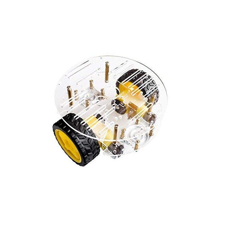
2WD Mini Round Double-Deck Smart Robot Car Chassis DIY Kit
Compact, lightweight 2WD chassis perfect for line follower builds. The double-deck design gives you room for an Arduino, motor driver, and IR sensor array on one clean platform.
What Is a Maze Solver Robot?
A maze solver robot must navigate through an unknown or known maze — a network of corridors, dead ends, and junctions — and find the exit (or a target cell) without a pre-drawn path to follow. Unlike a line follower, the maze solver must build a model of its environment, make decisions at junctions, handle dead ends by backtracking, and often remember which paths it has already explored.
Maze solving is a fundamentally more complex problem because the robot must maintain state across time. It needs to know not just its current situation, but its history — where it has been, which paths were dead ends, and how to retrace its route. This requires more memory, more sophisticated algorithms (such as flood-fill, Bellman-Ford, or the simple left/right-hand rule), and often an odometry or compass system to track position within the maze.
Micromouse competitions — where a small robot must solve a 16×16 grid maze as fast as possible — are the pinnacle of maze solver robotics. These machines cost lakhs of rupees, run at speeds exceeding 4 m/s, and use custom PCBs, optical encoders, gyroscopes, and flood-fill algorithms that take months to tune. But a simple maze solver using the left-hand rule and ultrasonic sensors is achievable for any intermediate Arduino maker.
Sensor Comparison: Line vs Maze Detection
Line Follower Sensors
Line followers use IR reflectance sensors: each sensor emits infrared light downward and measures the reflection. A black line absorbs IR (low reflection = sensor reads LOW or high ADC value depending on circuit), while a white surface reflects strongly (high reflection = sensor reads HIGH or low ADC value). An array of 5–8 sensors gives the position of the line relative to the robot’s centreline.
The TCRT5000 is the standard IR reflectance sensor module for line followers. It has a built-in emitter and detector and outputs both an analogue voltage (proportional to reflection intensity) and a digital output (above/below threshold set by an onboard potentiometer). For competitive line following, use 5–8 TCRT5000 sensors spaced 8–12 mm apart, giving you precise sub-millimetre line position sensing.
Maze Solver Sensors
Maze solvers need to detect walls on three sides (front, left, right). Ultrasonic sensors (HC-SR04) mounted on three sides of the robot measure wall distance — if distance is below a threshold (say 15 cm), there is a wall. IR distance sensors (Sharp GP2Y0A21) give faster, more consistent readings but are more expensive. The most capable maze solvers use Time-of-Flight (ToF) sensors (VL53L0X) which give accurate distance measurements at 50 Hz with a narrow beam — ideal for detecting walls precisely in narrow corridors.
4 Wheels Car Chassis Acrylic Frame
A sturdy 4WD acrylic chassis ideal for maze solver projects. The wider base provides better stability when making 90-degree turns at maze junctions.
Navigation Algorithms Explained
Line Follower: Bang-Bang Control
The simplest line following algorithm is bang-bang (on-off) control: if the line is to the left, turn left at maximum; if to the right, turn right at maximum; if centred, go straight. This produces a characteristic zig-zag motion as the robot continuously overcorrects. It works, but it is slow and inefficient. Bang-bang control is only useful as a starting point for beginners who have just assembled their first line follower chassis.
Line Follower: PID Control
PID (Proportional-Integral-Derivative) control is the gold standard for competitive line following. The controller calculates an error value (how far the line is from the sensor array centre), then applies three correction terms: Proportional (correction proportional to current error), Integral (correction proportional to accumulated past error, eliminates steady-state offset), and Derivative (correction proportional to rate of error change, dampens oscillations). Tuning Kp, Ki, and Kd constants — the classic challenge of control systems — allows the robot to follow tight curves at high speed without oscillating off the track.
Maze Solver: Left-Hand Rule (Wall Follower)
The left-hand rule (or right-hand rule) is the simplest maze solving algorithm: always keep one hand on the left (or right) wall as you navigate. This guarantees you will find the exit in any simply-connected maze (a maze with no loops — all walls connected to the outer boundary). The algorithm fails in multiply-connected mazes with islands, but it is simple to implement and reliable for most competition mazes designed for beginners.
Maze Solver: Flood-Fill Algorithm
Flood-fill is the algorithm used by top Micromouse robots. The maze is modelled as a grid. Each cell is assigned a value representing its Manhattan distance to the target cell. The robot starts at the far corner, reads its surroundings, updates the flood-fill values as walls are discovered, and always moves to the lowest-valued accessible neighbour. After the first run (exploration), the robot knows the complete maze structure and can plan the mathematically shortest path for its speed run. Flood-fill is provably optimal in finding the shortest path once all walls are known.
Hardware Requirements and Chassis
Line Follower Build List
- 2WD chassis with gear motors (minimum 100 RPM at operating voltage)
- IR sensor array (5 or 8 sensors) — TCRT5000 based
- Arduino Nano or Uno (Nano preferred for weight savings)
- L298N or TB6612FNG motor driver (TB6612FNG is more efficient)
- LiPo battery (7.4V, 1000–2000 mAh for good runtime)
- Voltage regulator (7805 or LM2596 for Arduino power)
Maze Solver Build List
- 2WD or 4WD chassis (4WD preferred for reliable in-place rotation)
- 3× HC-SR04 ultrasonic sensors (front, left, right)
- Arduino Uno or Mega (Mega preferred for maze memory)
- L298N motor driver
- Rotary encoders on drive wheels (for accurate distance/angle measurement)
- LiPo or 18650 Li-ion battery pack
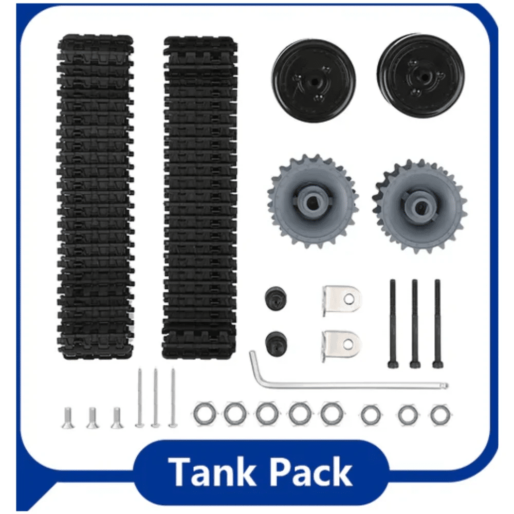
ACEBOTT ESP32 Tank Robot Car Expansion Pack
Upgrade your robot with the ACEBOTT ESP32 expansion pack. The tank-style treads give superior traction for maze solving, while the ESP32 provides WiFi for real-time maze data logging.
PID Control for Line Following
Here is a complete Arduino PID line follower implementation for a 5-sensor array (sensors on pins A0–A4, digital outputs, LOW = on line):
// PID Line Follower - 5 sensor array
#define KP 25.0
#define KI 0.0
#define KD 15.0
#define BASE_SPEED 180
#define MAX_SPEED 255

int sensorPins[] = {A0, A1, A2, A3, A4};
int weights[]    = {-2, -1, 0, 1, 2};  // position weights

float lastError = 0, integral = 0;

void setup() {
  // Motor pins (L298N: IN1-IN4, ENA, ENB)
  for (int i = 2; i <= 7; i++) pinMode(i, OUTPUT);
}

float readLinePosition() {
  int sum = 0, count = 0;
  for (int i = 0; i < 5; i++) {
    int val = (digitalRead(sensorPins[i]) == LOW) ? 1 : 0;
    sum += weights[i] * val;
    count += val;
  }
  return (count == 0) ? lastError : (float)sum / count;
}

void setMotors(int left, int right) {
  left  = constrain(left,  0, MAX_SPEED);
  right = constrain(right, 0, MAX_SPEED);
  // Left motor forward
  digitalWrite(2, HIGH); digitalWrite(3, LOW);
  analogWrite(5, left);
  // Right motor forward
  digitalWrite(4, HIGH); digitalWrite(7, LOW);
  analogWrite(6, right);
}

void loop() {
  float error = readLinePosition();
  integral += error;
  float derivative = error - lastError;
  float correction = KP*error + KI*integral + KD*derivative;
  lastError = error;
  setMotors(BASE_SPEED - correction, BASE_SPEED + correction);
}
Start with Kp=25, Kd=15, Ki=0. Increase Kp until the robot oscillates, then increase Kd to dampen the oscillation. Only add Ki if the robot drifts off centre on long straight sections. Most competition line followers use Ki=0 — the integral term can cause windup in curves.
Maze Solving: Left-Hand Rule in Arduino
Here is the state machine logic for left-hand rule maze solving with three HC-SR04 sensors:
// Left-Hand Rule Maze Solver
#define TRIG_F 2  #define ECHO_F 3  // Front
#define TRIG_L 4  #define ECHO_L 5  // Left
#define TRIG_R 6  #define ECHO_R 7  // Right
#define WALL_DIST 15  // cm threshold

long readCM(int trig, int echo) {
  digitalWrite(trig, LOW); delayMicroseconds(2);
  digitalWrite(trig, HIGH); delayMicroseconds(10);
  digitalWrite(trig, LOW);
  return pulseIn(echo, HIGH) / 58;
}

void loop() {
  long front = readCM(TRIG_F, ECHO_F);
  long left  = readCM(TRIG_L, ECHO_L);
  long right = readCM(TRIG_R, ECHO_R);

  bool wallFront = front < WALL_DIST;
  bool wallLeft  = left  < WALL_DIST;
  bool wallRight = right < WALL_DIST;

  if (!wallLeft) {
    turnLeft();    // Left wall open: take it
  } else if (!wallFront) {
    goForward();   // Left wall, no front wall: go straight
  } else if (!wallRight) {
    turnRight();   // Both left and front blocked: turn right
  } else {
    turnAround();  // Dead end: reverse direction
  }
}
Each turn function drives the motors for a calibrated time or encoder count to rotate exactly 90 degrees in place. Accurate turns are critical — a 5-degree error compounds over multiple junctions and causes the robot to miss wall detections.
Performance, Speed, and Competition Tips
Line Follower Speed Tips
The main limiter for line follower speed is curve detection lag. Reduce sensor-to-ground height to 3–5 mm for sharper contrast readings. Use analogue sensor readings (not just digital) for weighted averaging — this gives sub-sensor-pitch position resolution. Add a forward-looking sensor pair to detect upcoming junctions earlier and begin turning before the lead sensor reaches the junction.
Maze Solver Accuracy Tips
Accurate 90-degree turns are the hardest part of maze solving. Use wheel encoders to count rotations precisely. Calibrate on a known surface — motor speed varies with battery voltage, so use a voltage-compensated PWM value or closed-loop speed control. Add a gyroscope (MPU6050) for heading correction: if the gyro says you have only turned 85 degrees, continue the turn until it reads 90.
Which Should You Build First?
Start with a line follower. It teaches you the fundamentals of sensor reading, motor control, and feedback control (PID). The hardware is simpler and cheaper. Competition tracks are widely available at Indian college robotics events (Techniche, Kshitij, Techfest). Once you have a solid line follower with PID, move to maze solving — the motor control skills transfer directly, and you add the algorithmic challenge of navigation and memory management.

ACEBOTT ESP32 Basic Starter Kit – QE201
An all-in-one starter kit with the ESP32, sensors, and components needed to build your first line follower or maze solver. Perfect for students participating in college robotics competitions.
Frequently Asked Questions
Which is harder — a line follower or maze solver?
A maze solver is significantly harder. Line following is a pure control problem: read sensors, compute PID, set motor speeds. Maze solving adds algorithmic complexity (graph traversal, backtracking, memory management) and requires precise odometry for reliable navigation through junctions. Plan for 2–3× more development time for a maze solver.
Can the same chassis be used for both?
Yes, with software changes and sensor swaps. Use a 2WD chassis with differential drive. For line following, mount an IR array underneath. For maze solving, replace the IR array with ultrasonic sensors on three sides. The motor driver, Arduino, and power system remain the same.
What is the best Arduino for a line follower?
Arduino Nano is ideal for line followers — lightweight, compact, and has enough analog pins for a 5-sensor array plus digital outputs for a motor driver. For a maze solver with flood-fill and encoder tracking, use an Arduino Mega for its larger program memory (256 KB flash) and more UART ports.
How do I stop my line follower from losing the line at junctions?
Junctions confuse simple line followers because multiple sensors read the line simultaneously. Implement junction detection logic: if all sensors read the line at once, you are at a junction. Then execute the appropriate turn command (based on route instructions) rather than running PID. Store the turn sequence in EEPROM if you know the route in advance.
Does a maze solver need encoders?
Not strictly, but without encoders you rely on timed turns for 90-degree junctions, which drift significantly over multiple turns. Even cheap optical encoders (LM393 + slotted disc) dramatically improve turn accuracy. For serious competition, magnetic encoders (AS5048A) on the motor shafts give 14-bit resolution and are extremely reliable.
Both line follower and maze solver robots are outstanding projects for learning autonomous systems, sensor integration, and control theory. The line follower excels as a fast, competition-ready machine once PID is tuned. The maze solver develops your algorithmic thinking and is the gateway to advanced robotics research. Start with the parts available at Zbotic’s Robotics & Automation category and build your way from a simple bang-bang line follower to a full flood-fill maze solver — the journey is as rewarding as the destination.


Add comment