
The concept of IoT predictive maintenance vibration sensor systems is transforming how Indian manufacturing plants approach equipment reliability. Instead of waiting for a machine to break down — causing costly production halts — vibration-based condition monitoring lets you detect early signs of bearing wear, imbalance, and misalignment weeks before a catastrophic failure occurs. In this comprehensive guide, we will build a complete predictive maintenance system using an ESP32 and vibration sensors, covering everything from sensor selection to cloud-based anomaly detection.
What Is Predictive Maintenance and Why It Matters in India
Predictive maintenance (PdM) is a condition-based maintenance strategy where you monitor the actual health of equipment and intervene only when the data indicates an impending failure. This is fundamentally different from:
- Reactive maintenance: Fix it after it breaks. Expensive, disruptive, often unsafe.
- Preventive maintenance: Replace/service on a fixed schedule regardless of condition. Wastes money on healthy components.
- Predictive maintenance: Monitor continuously and act only when needed. Maximises component life and minimises unplanned downtime.
For Indian manufacturing — whether in Pune’s automotive belt, Ludhiana’s bicycle industry, or Chennai’s textile mills — unplanned machine downtime can cost anywhere from ₹50,000 to ₹10 lakh per hour depending on the production line. With the cost of ESP32-based vibration monitoring nodes under ₹2,000 per machine, the ROI is almost immediate. The Ministry of Heavy Industries’ PLI scheme is actively pushing Industry 4.0 adoption, making this the perfect time to implement IoT PdM systems.
Vibration Analysis Fundamentals for Industrial IoT
Machines generate vibration signatures that are as unique as fingerprints. A healthy motor running at 1450 RPM has a specific vibration profile at 24.2 Hz (the fundamental frequency) and its harmonics. When a bearing starts to fail, specific defect frequencies appear in the spectrum. Here are the key vibration parameters:
Key Metrics to Monitor
- RMS (Root Mean Square) Amplitude: Overall vibration intensity. Rising RMS is often the first sign of developing trouble. ISO 10816 defines acceptable RMS velocity ranges for different machine classes.
- Peak Acceleration (g): Impulsive events like bearing impacts show up as spikes in acceleration. Measured in g (9.8 m/s²).
- Crest Factor: Ratio of peak to RMS. A rising crest factor with stable RMS indicates developing bearing damage before it becomes severe enough to raise overall RMS.
- Frequency Spectrum (FFT): The frequency domain representation. Bearing defect frequencies (BPFO, BPFI, BSF, FTF) are calculated from bearing geometry and shaft speed.
- Kurtosis: Statistical measure of impulsiveness. Early bearing faults spike kurtosis before any RMS change.
Choosing the Right Vibration Sensor
Several sensor types can be used with ESP32 for vibration monitoring. Each has its place in a PdM system:
| Sensor Type | Interface | Frequency Range | Best For |
|---|---|---|---|
| ADXL345 | I2C/SPI | 0–1600 Hz (3200 Hz max) | Low-cost bearing monitoring |
| MPU6050 | I2C | 0–1000 Hz (hardware LPF) | General vibration + gyro |
| ADXL355 | SPI | 0–1000 Hz, low noise | High-accuracy monitoring |
| SW-420 | Digital GPIO | Threshold only | Simple vibration detection |
| Piezo sensor | Analog ADC | 0–5000+ Hz | High-frequency fault detection |
For most industrial PdM applications in India, the ADXL345 or MPU6050 with SPI interface provides the best balance of cost, bandwidth, and ESP32 compatibility. The ESP32’s 240 MHz dual-core processor can sample these sensors at 3200 samples/second and perform FFT analysis in real time.
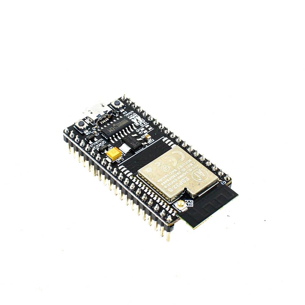
Ai Thinker NodeMCU-32S-ESP32 Development Board – IPEX Version
The IPEX version allows connecting an external antenna — essential for factory floor deployments where the node is mounted inside a metal enclosure on a machine.
Hardware Setup: ESP32 + Vibration Sensors
For this project, we use an ESP32 development board with an MPU6050 accelerometer/gyroscope over I2C. The ESP32’s dual-core architecture lets us run data acquisition on Core 1 and WiFi/MQTT publishing on Core 0 simultaneously, eliminating the jitter that degrades FFT accuracy.
Wiring Diagram
MPU6050  -->  ESP32
VCC      -->  3.3V
GND      -->  GND
SCL      -->  GPIO 22 (I2C SCL)
SDA      -->  GPIO 21 (I2C SDA)
INT      -->  GPIO 4  (Data Ready interrupt)
AD0      -->  GND     (I2C address: 0x68)
Mount the MPU6050 directly on the machine housing using a magnet mount or epoxy. Avoid mounting through rubber gaskets or vibration isolators — you want the sensor to be rigidly coupled to the machine so it picks up the actual vibration signature, not a filtered version of it.
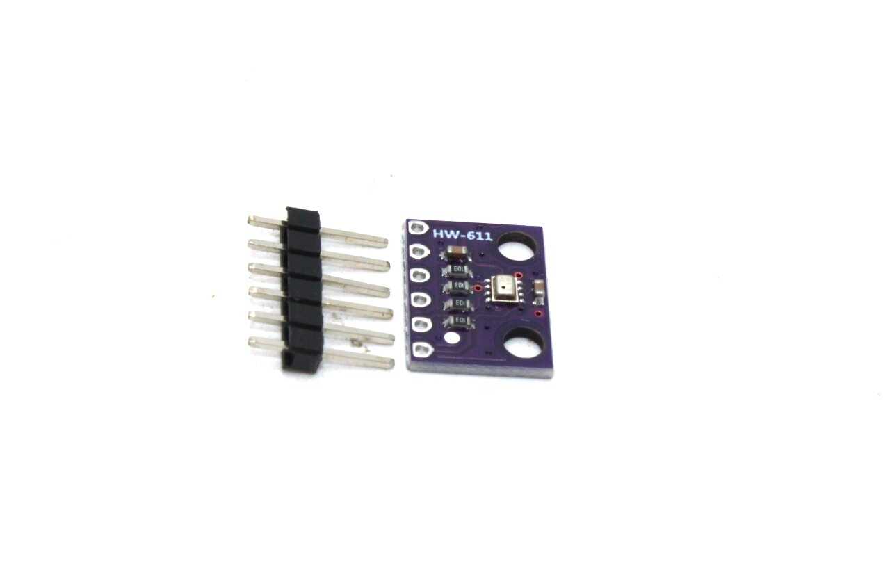
BMP280 Barometric Pressure and Altitude Sensor I2C/SPI Module
Pair with your vibration sensor to simultaneously monitor temperature and humidity near the motor — heat buildup is often a co-indicator of bearing failure.
Firmware: FFT-Based Frequency Analysis
The core of any vibration-based PdM system is frequency domain analysis. We use the ESP32’s hardware DSP capabilities and the arduinoFFT library to transform time-domain accelerometer data into a frequency spectrum:
#include <Wire.h>
#include <MPU6050.h>
#include <WiFi.h>
#include <PubSubClient.h>
#include <arduinoFFT.h>
#include <ArduinoJson.h>

// FFT parameters
#define SAMPLES 512          // Must be power of 2
#define SAMPLING_FREQ 3000.0 // Hz - must be 2x max frequency of interest

double vReal[SAMPLES];
double vImag[SAMPLES];

ArduinoFFT<double> FFT = ArduinoFFT<double>(vReal, vImag, SAMPLES, SAMPLING_FREQ);
MPU6050 mpu;

const char* MQTT_BROKER = "broker.hivemq.com";
const char* MQTT_TOPIC  = "factory/machine1/vibration";

// RMS calculation
float calculateRMS(double* data, int len) {
  double sum = 0;
  for (int i = 0; i < len; i++) sum += data[i] * data[i];
  return sqrt(sum / len);
}

// Kurtosis calculation
float calculateKurtosis(double* data, int len) {
  double mean = 0, variance = 0, kurtosis = 0;
  for (int i = 0; i < len; i++) mean += data[i];
  mean /= len;
  for (int i = 0; i < len; i++) {
    double diff = data[i] - mean;
    variance += diff * diff;
    kurtosis += diff * diff * diff * diff;
  }
  variance /= len;
  kurtosis /= len;
  return (variance == 0) ? 0 : kurtosis / (variance * variance);
}

void collectAndAnalyze() {
  int16_t ax, ay, az, gx, gy, gz;
  unsigned long sampleInterval = 1000000 / SAMPLING_FREQ; // microseconds

  // Collect SAMPLES data points at SAMPLING_FREQ
  for (int i = 0; i < SAMPLES; i++) {
    unsigned long t = micros();
    mpu.getMotion6(&ax, &ay, &az, &gx, &gy, &gz);
    vReal[i] = az / 16384.0; // Convert to g (scale for +/-2g range)
    vImag[i] = 0.0;
    while (micros() - t < sampleInterval); // Precise timing
  }

  // Compute statistics on raw data
  float rms = calculateRMS(vReal, SAMPLES);
  float kurtosis = calculateKurtosis(vReal, SAMPLES);

  // FFT processing
  FFT.windowing(FFTWindow::Hann, FFTDirection::Forward);
  FFT.compute(FFTDirection::Forward);
  FFT.complexToMagnitude();

  // Find dominant frequency
  double dominantFreq = FFT.majorPeak();

  // Publish results via MQTT
  StaticJsonDocument<256> doc;
  doc["machine"]   = "Pump-1";
  doc["rms_g"]     = rms;
  doc["kurtosis"]  = kurtosis;
  doc["peak_hz"]   = dominantFreq;
  doc["timestamp"] = millis();

  // Anomaly detection: alert if kurtosis > 4 (bearing fault indicator)
  if (kurtosis > 4.0) {
    doc["alert"] = "BEARING_FAULT_SUSPECTED";
    Serial.println("ALERT: Bearing fault signature detected!");
  }

  char jsonBuffer[256];
  serializeJson(doc, jsonBuffer);
  // mqttClient.publish(MQTT_TOPIC, jsonBuffer);
  Serial.println(jsonBuffer);
}
This firmware samples the Z-axis acceleration at 3000 Hz, computes FFT on 512 samples (giving 5.8 Hz frequency resolution), and publishes key metrics including kurtosis (an early bearing fault indicator) via MQTT. The MQTT payload is compact enough to work on constrained bandwidth connections.
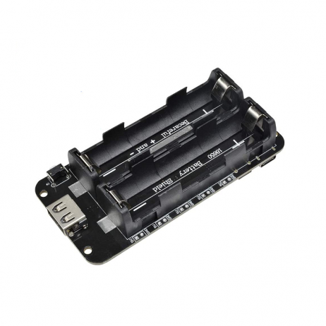
2 x 18650 Lithium Battery Shield for ESP32/ESP8266
Power your vibration monitoring node from a battery so it keeps collecting data even during plant power outages — critical for monitoring startup transients after power restoration.
Cloud Integration and Alert Systems
The vibration data from your ESP32 nodes needs to flow to a platform where you can visualise trends, set thresholds, and receive alerts. Here are the best options for Indian deployments:
1. ThingsBoard (Open Source, Self-Hosted)
ThingsBoard Community Edition can be installed on a low-cost AWS EC2 t3.micro instance (eligible for free tier). It supports MQTT natively, provides time-series dashboards, and has a powerful rule engine for anomaly alerting. This is the best choice for factories that cannot share production data with third-party cloud providers.
2. AWS IoT Core + Amazon Lookout for Equipment
AWS provides a fully managed IoT pipeline. ESP32 publishes to AWS IoT Core via MQTT over TLS, data flows to S3, and Amazon Lookout for Equipment applies ML to detect anomalies automatically. The pay-per-use model works well for deployments under 100 machines.
3. Grafana + InfluxDB
A lightweight stack for small deployments. InfluxDB stores time-series vibration data efficiently, Grafana provides dashboards and alerting. Both can run on a ₹500/month VPS. Telegraf acts as the MQTT bridge from ESP32 to InfluxDB.
Setting Alert Thresholds
Base your initial thresholds on ISO 10816-3 for industrial machines above 15 kW. For most pumps and motors in Indian factories:
- Zone A (New): RMS velocity < 2.3 mm/s
- Zone B (Acceptable): 2.3–4.5 mm/s
- Zone C (Warning): 4.5–7.1 mm/s — schedule maintenance
- Zone D (Danger): > 7.1 mm/s — stop machine immediately
For bearing-specific monitoring, use kurtosis > 4.0 as your early warning trigger, and kurtosis > 8.0 as your critical alert threshold.
Frequently Asked Questions
What sampling rate do I need for bearing fault detection on a 1450 RPM motor?
For a standard 6205 bearing on a 1450 RPM shaft, the Ball Pass Frequency Outer Race (BPFO) is approximately 78 Hz. To detect this and its harmonics up to the 10th order (780 Hz), you need a sampling rate of at least 1600 Hz (per Nyquist theorem). We recommend 3200 Hz for a comfortable margin and to capture higher-frequency defects in the bearing’s ultrasonic signature.
How accurate is ESP32 vibration monitoring compared to industrial systems?
ESP32 with a 12-bit ADC and ADXL345/MPU6050 is suitable for detecting developing faults (Stage 2 and Stage 3 of a 4-stage bearing degradation model). It will miss very early Stage 1 defects that industrial systems with 24-bit ADCs and IEPE accelerometers can detect. However, for the cost difference of 100x, the ESP32 system catches problems early enough to prevent unexpected failures in most industrial applications.
Can I run machine learning on the ESP32 itself for fault detection?
Yes, using TensorFlow Lite for Microcontrollers (TFLite Micro). You can train a simple autoencoder or classification model on known good and fault vibration data, then deploy it to the ESP32. The dual-core 240 MHz processor and 520 KB SRAM can run small neural networks for anomaly detection. This eliminates cloud dependency for edge inference.
How many vibration monitoring nodes can one ESP32 gateway manage?
If using ESP32-to-ESP32 communication via ESP-NOW, a single gateway ESP32 can handle up to 20 sensor nodes. With WiFi mesh (using ESP-IDF’s esp_mesh), theoretical limits are much higher, but practical deployments typically work best under 32 nodes per gateway to maintain data freshness.
Start Your Predictive Maintenance Project Today
Zbotic.in supplies the ESP32 modules, sensors, and accessories you need to build industrial-grade predictive maintenance systems at hobbyist prices. Browse our IoT and sensor collection and start protecting your plant’s equipment today.


Add comment