
Accurate motor speed measurement is the foundation of any closed-loop control system. Without knowing how fast your motor is actually spinning, you cannot correct for load variations, battery voltage sag, or motor-to-motor differences in a multi-wheel robot. The Hall effect sensor — combined with a small magnet mounted on the motor shaft — gives you a clean, noise-immune digital pulse for every revolution, and Arduino’s hardware interrupts turn those pulses into accurate RPM readings.
This tutorial covers the complete system: choosing the right Hall effect sensor, mounting it correctly, wiring to Arduino, writing interrupt-driven code, calculating RPM, and implementing a basic PID speed controller that uses the Hall sensor as feedback.
1. How Hall Effect Sensors Work
The Hall effect was discovered by Edwin Hall in 1879. When a current-carrying conductor is placed in a perpendicular magnetic field, a voltage (the Hall voltage) develops across the conductor perpendicular to both the current and the magnetic field. In a Hall effect sensor IC, this microscopic voltage is amplified and compared against a threshold to produce a clean digital output.
For motor speed measurement, we attach a small neodymium magnet to the motor shaft (or to a disc mounted on the shaft). As the shaft rotates, the magnet passes the Hall sensor once per revolution (or once per pole for multi-magnet arrangements). Each pass switches the sensor’s output from HIGH to LOW (or triggers a pulse edge). Arduino counts these edges over a known time interval to calculate RPM.
Why Hall Effect Instead of Optical Encoder?
Both work well for speed measurement. Hall effect sensors have several advantages for motor applications:
- Dust and contamination tolerant — no optical path to block
- Wide air gap tolerance — works 2–5 mm away from the magnet
- Vibration resistant — no encoder disk to crack
- Very low cost — a single A3144 or SS49E costs under ₹10
Optical encoders have higher resolution (more pulses per revolution) and are better for absolute position sensing. For speed-only measurement, Hall sensors are simpler and more robust.
2. Sensor Types: Latching vs Unipolar vs Linear
Latching (Bipolar) Hall Sensors — A3141, A3144, US1881
Latching sensors have two stable output states. They turn ON when the North pole of a magnet approaches, and turn OFF only when the South pole approaches. They stay in their current state even after the magnet is removed. Best for speed counting with a single magnet — you get one clean pulse per revolution with a sharp edge for interrupt triggering.
The A3144 (or its equivalent A44E, SS41F) is the most widely available and cheapest option in India, working from 4.5–24 V with open-collector output. The US1881 is a popular alternative at 3.5–24 V.
Unipolar Hall Sensors — SS441A, OH137
Unipolar sensors activate (output goes LOW) when a magnetic field exceeds a threshold, and deactivate when the field drops below a release threshold (hysteresis). They only respond to one pole. Suitable for single-magnet speed counting but the output duty cycle varies with gap distance and magnet strength.
Linear (Analog) Hall Sensors — SS49E, A1302
Linear sensors output an analog voltage proportional to magnetic field strength. The output is 0–VCC (centered at VCC/2 with no field). Not suitable for clean digital speed counting without a comparator, but excellent for measuring magnetic field strength or as a current sensor (in a current-sensing transformer configuration).
3. Mounting the Magnet and Sensor
Magnet Selection
Use a small neodymium (N35 or stronger) disc magnet, typically 3–6 mm diameter and 2–3 mm thick. These are strong enough to trigger a Hall sensor at 3–5 mm air gap. Avoid ceramic ferrite magnets — they are weaker and require a smaller air gap, increasing mechanical risk of the sensor hitting the rotating assembly.
Attaching the Magnet to the Shaft
Three common methods:
- Epoxy directly to the shaft end — use cyanoacrylate (CA glue) or two-part epoxy. Clean the shaft with acetone first. Centre the magnet carefully to avoid imbalance at high speed.
- Press into a 3D-printed disc — print a disc that press-fits onto the motor shaft with a pocket for the magnet. This is the most repeatable and replaceable method.
- Attach to the rear of an encoder wheel — TT motors have a rear shaft that accepts a small disc. Mount the magnet on this disc.
Positioning the Sensor
Mount the Hall sensor on a rigid bracket so its sensitive face passes 2–4 mm from the rotating magnet. The sensor face (marked side, or flat side on through-hole packages) must face the magnet. Ensure the sensor body and leads cannot contact the rotating assembly at any point in the rotation. Use a hot-glue or bolt-mounted bracket — do not rely on the sensor leads for support.
4. Wiring to Arduino
The A3144 Hall sensor is a 3-pin device: VCC, GND, and OUTPUT (open-collector). For Arduino:
| A3144 Pin | Connect To | Notes |
|---|---|---|
| Pin 1 (VCC) | 5 V | A3144 needs 4.5–24 V; 5 V fine |
| Pin 2 (GND) | GND | Common ground with Arduino |
| Pin 3 (Output) | Arduino D2 or D3 | Add 10 kΩ pull-up to 5 V; output is open-collector |
Critical: The A3144 output is open-collector — it can pull LOW but cannot drive HIGH by itself. You must add a 10 kΩ pull-up resistor between the output pin and VCC, or enable Arduino’s internal pull-up (INPUT_PULLUP mode). Without this, the output pin floats HIGH-ish but with excessive noise.
For 3.3 V systems (ESP32, Arduino Due, STM32): use the US1881 (3.5 V minimum) or a level-shifted A3144, and add your pull-up resistor to 3.3 V, not 5 V.
5. Interrupt-Driven RPM Code
Polling a Hall sensor pin in the main loop is unreliable at motor speeds above ~100 RPM — the Arduino may miss pulses between loop iterations. Hardware interrupts guarantee every pulse is counted regardless of what the rest of the code is doing.
Arduino Uno/Nano has hardware interrupts on pins D2 (INT0) and D3 (INT1). Arduino Mega has interrupts on D2, D3, D18, D19, D20, D21.
// Hall Effect Sensor RPM Measurement
// A3144 sensor on Arduino D2 (INT0), output pulled HIGH via 10k resistor
// Each magnet pass creates a FALLING edge (output goes LOW)

const int HALL_PIN = 2;          // Hardware interrupt pin
const int SAMPLE_INTERVAL = 1000; // Calculate RPM every 1000 ms

volatile unsigned long pulseCount = 0;  // Incremented in ISR
unsigned long lastCalcTime = 0;
float rpm = 0.0;

void IRAM_ATTR hallISR() {
  pulseCount++;
}

void setup() {
  Serial.begin(115200);
  pinMode(HALL_PIN, INPUT_PULLUP);  // Enable pull-up resistor
  // Trigger ISR on FALLING edge (magnet arrives: output goes LOW)
  attachInterrupt(digitalPinToInterrupt(HALL_PIN), hallISR, FALLING);
  lastCalcTime = millis();
}

void loop() {
  unsigned long now = millis();
  if (now - lastCalcTime >= SAMPLE_INTERVAL) {
    // Disable interrupts briefly to read pulseCount atomically
    noInterrupts();
    unsigned long count = pulseCount;
    pulseCount = 0;
    interrupts();

    unsigned long elapsed = now - lastCalcTime;
    lastCalcTime = now;

    // 1 pulse per revolution, elapsed in ms
    // RPM = (pulses / elapsed_ms) * 60000
    rpm = ((float)count / elapsed) * 60000.0;

    Serial.print("RPM: ");
    Serial.println(rpm, 1);
  }
  // Do other robot work here — interrupts handle the counting
}
6. RPM Calculation and Averaging
Single Magnet (1 Pulse Per Revolution)
The formula above assumes one pulse per revolution. RPM = (pulses in interval) / (interval in minutes) = pulses × (60000 / interval_ms).
Multiple Magnets (N Pulses Per Revolution)
If you mount N magnets equally spaced around the shaft disk, divide by N:
const int MAGNETS_PER_REV = 4;  // 4 magnets on the disk
rpm = ((float)count / MAGNETS_PER_REV / elapsed) * 60000.0;
Moving Average for Stability
At low RPM, the sample interval may contain only a few pulses, making the reading noisy. A moving average smooths the output:
const int AVG_SIZE = 5;
float rpmHistory[AVG_SIZE] = {0};
int histIdx = 0;

float smoothedRPM() {
  rpmHistory[histIdx] = rpm;
  histIdx = (histIdx + 1) % AVG_SIZE;
  float sum = 0;
  for (int i = 0; i < AVG_SIZE; i++) sum += rpmHistory[i];
  return sum / AVG_SIZE;
}
Interval Length vs Resolution
Shorter sample intervals (100–200 ms) give faster response to speed changes but more noise at low RPM. Longer intervals (500–1000 ms) give smoother readings but slower response. For a robot, 200–500 ms is usually the best compromise for speed control loops.
7. PID Speed Control with Hall Feedback
With reliable RPM feedback, you can implement a PID controller that adjusts PWM duty cycle to maintain a target speed regardless of load or battery voltage.
// Simple PID Speed Controller
// Motor connected to L298N: ENA = D9 (PWM), IN1 = D7, IN2 = D8

const int PWM_PIN = 9;
const int IN1_PIN = 7;
const int IN2_PIN = 8;

float targetRPM = 150.0;  // Desired speed
float Kp = 0.5;           // Proportional gain — tune this
float Ki = 0.1;           // Integral gain
float Kd = 0.05;          // Derivative gain

float integral = 0;
float prevError = 0;
int pwmOut = 0;

void updatePID(float measuredRPM) {
  float error = targetRPM - measuredRPM;
  integral += error;              // Accumulate integral
  integral = constrain(integral, -1000, 1000);  // Prevent windup

  float derivative = error - prevError;
  prevError = error;

  float output = Kp * error + Ki * integral + Kd * derivative;
  pwmOut = constrain((int)pwmOut + (int)output, 0, 255);

  analogWrite(PWM_PIN, pwmOut);
}

void setup() {
  // ... (same as above plus motor pin setup)
  pinMode(PWM_PIN, OUTPUT);
  pinMode(IN1_PIN, OUTPUT);
  pinMode(IN2_PIN, OUTPUT);
  digitalWrite(IN1_PIN, HIGH);  // Forward direction
  digitalWrite(IN2_PIN, LOW);
}

void loop() {
  unsigned long now = millis();
  if (now - lastCalcTime >= 200) {  // 200ms control loop
    noInterrupts();
    unsigned long count = pulseCount;
    pulseCount = 0;
    interrupts();

    float elapsed = now - lastCalcTime;
    lastCalcTime = now;
    rpm = (count / elapsed) * 60000.0;

    updatePID(rpm);

    Serial.print("Target: "); Serial.print(targetRPM);
    Serial.print(" | Actual: "); Serial.print(rpm, 0);
    Serial.print(" | PWM: "); Serial.println(pwmOut);
  }
}
Tuning PID Gains
- Start with Kp=0.5, Ki=0, Kd=0. Increase Kp until the speed oscillates around the setpoint.
- Reduce Kp by ~30%, then add Ki=0.05 to eliminate steady-state error.
- Add Kd=0.02 if oscillation persists.
- Repeat in small increments until the motor reaches setpoint quickly with minimal overshoot.
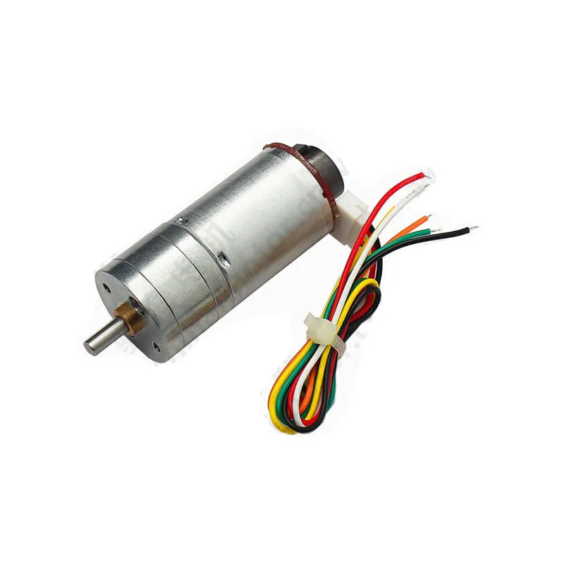
25GA-370 12V DC Reducer Gear Motor with Encoder
This gear motor includes a built-in quadrature encoder — an upgrade over a single Hall sensor, giving both speed and direction feedback for precise closed-loop control.
8. Multi-Magnet Setup for Higher Resolution
At low motor speeds (below 50 RPM), a single magnet generates so few pulses per sample interval that speed resolution is poor. For example, at 30 RPM with a 500 ms sample interval, you get only 0.25 pulses — clearly not useful.
Adding more magnets equally spaced around the shaft disk multiplies the pulse rate by the number of magnets. With 8 magnets and a 500 ms sample, you get 2 pulses at 30 RPM — still low but measurable. With 16 or 32 magnets (simulated by printing a magnetic encoder strip), resolution becomes excellent even at low speeds.
Alternatively, use a Hall effect IC designed for quadrature encoding (like the AH3503) that outputs two 90°-phase-shifted signals — this gives both speed and direction from a single multi-pole magnet ring, exactly like a professional quadrature encoder.
9. Troubleshooting
RPM reads zero
- Check that the Hall sensor output is pulled HIGH (10 kΩ to VCC). Measure with a multimeter — should read ~5 V with no magnet.
- Verify the magnet passes within 2–4 mm of the sensor face (marked side).
- Confirm you are triggering on FALLING (magnet activates) not RISING.
- Try both poles of the magnet — latching sensors only respond to the correct pole.
RPM reads erratically / double counts
- Mechanical vibration is causing the sensor to trigger multiple times per magnet pass. Add a small software debounce: inside the ISR, reject triggers less than 5 ms after the last trigger.
- The magnet is too strong and the sensor is saturating before the magnet arrives — increase the air gap slightly.
RPM is consistently wrong by a fixed factor
- You have N magnets but the code assumes 1 per revolution — divide by N.
- The gear ratio between the motor shaft and the disk is not accounted for.
Motor control jitters when Hall sensor is active
- Motor interference is coupling into the Hall sensor signal wire. Use a twisted pair for the sensor signal and GND, and keep sensor wires physically separated from motor power wires.
- Add a 100 nF ceramic capacitor between the Hall sensor output pin and GND, close to the sensor.

25GA-370 12V 12RPM DC Reducer Gear Motor
At 12 RPM, this slow gear motor is an excellent candidate for testing Hall effect speed measurement — low RPM makes pulse timing easy to visualize and debug on a Serial plotter.
Frequently Asked Questions
Which interrupt pin should I use on Arduino Uno?
Arduino Uno has hardware interrupts on D2 and D3 only. For a two-motor encoder system, use D2 for one motor and D3 for the other. For more motors, use Arduino Mega which has six interrupt-capable pins.
Can I use a Hall sensor with an ESP32?
Yes. ESP32 supports interrupts on all GPIO pins. Use attachInterrupt(digitalPinToInterrupt(PIN), ISR, FALLING) just like Arduino. Note that ESP32 is 3.3 V logic — use a Hall sensor compatible with 3.3 V supply or add a level shifter.
What is the difference between A3141, A3142, A3143, and A3144?
All are Allegro latching Hall sensors with the same pinout. They differ in magnetic sensitivity (operate and release points in Gauss). A3144 has the highest sensitivity (operates at lower magnetic field), making it easiest to use with weaker or more distant magnets. A3141 requires the strongest field.
Can I measure motor RPM without a magnet?
Yes — a brushed DC motor generates electrical commutation ripple that can be filtered and counted. But this is more complex and less reliable than a Hall sensor setup. For brushless motors, the ESC’s telemetry output or back-EMF zero-crossing detection is used. For brushed motors, a Hall sensor and magnet is the simplest reliable approach.
How accurate is the RPM measurement?
With a single magnet and a 500 ms sample interval, resolution is ±2 RPM at 200 RPM (1 pulse = 1/8.33 minutes → 1 RPM change). With a 4-magnet setup, resolution improves to ±0.5 RPM. For higher accuracy at low speeds, use a longer sample interval or increase the number of magnets.
Conclusion
Hall effect sensors transform motor speed measurement from an analogue problem into a simple digital pulse-counting task that Arduino handles natively through hardware interrupts. The A3144 sensor, a 3 mm neodymium magnet, a 10 kΩ pull-up resistor, and 20 lines of code are all you need to go from open-loop motor control to fully closed-loop PID speed control.
This speed feedback foundation enables accurate differential drive robots that drive straight, multi-motor systems that synchronise wheel speeds, and any application requiring repeatable motion — odometry, conveyor speed control, centrifuge RPM regulation, and more.
Shop motors with encoders at Zbotic: We stock 25GA gear motors with built-in quadrature encoders, stepper motors, and all the driver modules you need. Visit zbotic.in/product-category/motors-drivers-pumps-actuators/ for fast delivery across India.


Add comment