
A flex sensor glove that can recognise hand gestures is one of the most impressive and practical wearable electronics projects you can build with Arduino. Imagine controlling a robotic arm with your own hand movements, operating a drone with finger gestures, or building a sign language translator that converts hand signs to text — all of this becomes possible with flex sensors and a microcontroller. This step-by-step guide covers everything from understanding how flex sensors work to building a complete gesture recognition glove with Arduino, wireless communication, and gesture mapping.
Flex sensors (also called bend sensors) are resistive strips whose electrical resistance changes when bent. Mounted on the fingers of a glove, they measure how much each finger is curled. By reading five flex sensors simultaneously, your Arduino can detect dozens of distinct hand gestures and translate them into control commands for robots, computers, or any other device.
1. How Flex Sensors Work
A flex sensor is a thin, flexible strip made from a conductive polymer film printed on a polyester substrate. The conductive layer contains a resistive element whose resistance increases when the strip is bent. In the flat (unbent) position, resistance is at its minimum; as the strip curves, microcracks form in the conductive material, increasing resistance proportionally to the bend angle.
Most standard flex sensors (like the Spectra Symbol 2.2-inch variety) have:
- Flat resistance: ~25 kΩ (varies by manufacturer — always measure yours)
- Fully bent resistance: ~100–125 kΩ at 90° bend
- Resistance change: ~75–100 kΩ over full range
- Operating voltage: Up to 5V (use below 1V for lower power / longevity)
- Life: >1 million bend cycles at recommended voltage
Since the Arduino cannot directly measure resistance, we use a voltage divider circuit to convert resistance to voltage, which the analogRead() function can read. Pairing each flex sensor with a fixed resistor of comparable value (typically 10–47 kΩ) creates a voltage divider whose output voltage varies with bend angle.
2. Types of Flex Sensors: 2.2-inch vs 4.5-inch
Flex sensors are commonly available in two lengths:
- 2.2-inch (56mm): Suitable for fingers — fits one finger joint when mounted along the finger dorsum. Best for typical hand gesture gloves.
- 4.5-inch (114mm): Longer, for spanning multiple finger joints or for larger components. Can cover two joints of a finger for enhanced sensing range. Also used in robotics and prosthetics.
For a standard gesture glove, the 2.2-inch sensor per finger is the most practical. If you want to capture both the MCP (knuckle) and PIP (middle) joint of each finger, use 4.5-inch sensors or two 2.2-inch sensors per finger (requiring 10 analog inputs — use a multiplexer like the CD4051 or MCP3008).
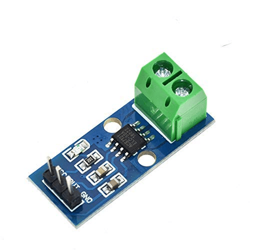
30A Range Current Sensor Module ACS712
Monitor battery current draw in your wireless glove project — the ACS712 measures real-time power consumption for battery life optimization.
3. Materials Required
Core Components
- 5× Flex sensors (2.2-inch, one per finger)
- Arduino Nano or Arduino Uno
- 5× 47kΩ resistors (for voltage divider)
- Thin cotton or nylon glove (snug fit, 5-finger)
- Velcro straps or fabric tape for mounting
- Insulated hookup wire (flexible, thin — 26 AWG works well)
- Breadboard or custom PCB
- USB cable for programming
Optional (Recommended) Additions
- HC-05 or HC-06 Bluetooth module (for wireless)
- MPU6050 IMU sensor (for wrist orientation / additional gesture data)
- LiPo battery + charging module (for untethered operation)
- 0.96-inch OLED display (show gesture name locally)
- Vibration motor (haptic feedback)
4. Circuit Design: Voltage Divider for Flex Sensors
Each flex sensor connects in a voltage divider with a fixed resistor. The Arduino reads the midpoint voltage:
        5V
         |
        [Flex Sensor]  (resistance varies with bend)
         |
         +-----> Arduino Analog Pin (A0–A4)
         |
        [47kΩ fixed resistor]
         |
        GND
When the finger is straight: flex resistance ≈ 25kΩ, voltage at midpoint = 5V × (47/(25+47)) ≈ 3.26V → analogRead ≈ 668.
When the finger is bent: flex resistance ≈ 100kΩ, voltage at midpoint = 5V × (47/(100+47)) ≈ 1.60V → analogRead ≈ 326.
So analogRead values decrease as the finger bends more. The exact values depend on your specific sensors — calibration is essential.
5-finger wiring connections:
| Finger | Analog Pin |
|---|---|
| Thumb | A0 |
| Index | A1 |
| Middle | A2 |
| Ring | A3 |
| Pinky | A4 |
5. Glove Assembly and Sensor Mounting
Mounting flex sensors correctly on the glove is critical for consistent readings:
Method 1: Sewn Channels
Sew thin fabric tubes (channels) along the dorsal (back) side of each finger — just wide enough for the flex sensor to slide in. This gives clean, reproducible sensor positioning and the sensor won’t slide out. Leave the sensor terminals exposed at the wrist end.
Method 2: Velcro or Elastic Tape
For quick prototyping, secure sensors with small pieces of velcro or elastic fabric tape along the finger back. This is removable and adjustable but may shift over extended wear.
Method 3: Shrink Tubing
Slide the flex sensor inside appropriately sized heat-shrink tubing, then sew or glue the tubing to the glove. The tubing protects the sensor and keeps it aligned.
Key mounting rules:
- Mount sensors on the dorsal (back) side of fingers, not the palm side
- Position the active sensing area over the proximal phalange (first finger segment from knuckle)
- Ensure sensors can flex without kinking — gentle curves only
- Route wires along the back of the hand, secured with fabric tape, to a wrist-mounted enclosure holding the Arduino
- Use flexible, thin 26 AWG wire to avoid restricting hand movement
6. Arduino Code: Reading Flex Sensor Values
// Flex Sensor Glove - Raw Reading
const int FLEX_THUMB  = A0;
const int FLEX_INDEX  = A1;
const int FLEX_MIDDLE = A2;
const int FLEX_RING   = A3;
const int FLEX_PINKY  = A4;

const int VCC = 5000;     // Supply voltage in mV
const int R_DIV = 47000;  // Fixed resistor value (ohms)

void setup() {
  Serial.begin(9600);
  pinMode(FLEX_THUMB,  INPUT);
  pinMode(FLEX_INDEX,  INPUT);
  pinMode(FLEX_MIDDLE, INPUT);
  pinMode(FLEX_RING,   INPUT);
  pinMode(FLEX_PINKY,  INPUT);
}

int readFlexResistance(int pin) {
  int raw = analogRead(pin);
  float voltage = raw * (VCC / 1023.0);  // Convert to mV
  int flexR = R_DIV * (VCC / voltage - 1.0);  // Calculate flex resistance
  return flexR;
}

void loop() {
  int thumb  = readFlexResistance(FLEX_THUMB);
  int index  = readFlexResistance(FLEX_INDEX);
  int middle = readFlexResistance(FLEX_MIDDLE);
  int ring   = readFlexResistance(FLEX_RING);
  int pinky  = readFlexResistance(FLEX_PINKY);

  Serial.print("Thumb: "); Serial.print(thumb);
  Serial.print(" Index: "); Serial.print(index);
  Serial.print(" Middle: "); Serial.print(middle);
  Serial.print(" Ring: "); Serial.print(ring);
  Serial.print(" Pinky: "); Serial.println(pinky);

  delay(200);
}
Run this code and open the Serial Monitor while flexing each finger one at a time. Note the resistance values when each finger is fully extended and fully bent — you will need these for calibration.
7. Calibrating Flex Sensors
Each flex sensor is slightly different, and sensor response varies with mounting. Calibration maps raw resistance to a 0–100 “bend percentage” for easier gesture logic:
// Calibration values — measure yours with the raw reading sketch
// Format: {straight_resistance, bent_resistance}
int thumbCal[2]  = {25000, 95000};
int indexCal[2]  = {23000, 93000};
int middleCal[2] = {24000, 97000};
int ringCal[2]   = {26000, 100000};
int pinkyCal[2]  = {22000, 88000};

int getBendPercent(int resistance, int* cal) {
  int percent = map(resistance, cal[0], cal[1], 0, 100);
  return constrain(percent, 0, 100);
}

// Usage in loop:
// int thumbBend  = getBendPercent(readFlexResistance(FLEX_THUMB),  thumbCal);
// int indexBend  = getBendPercent(readFlexResistance(FLEX_INDEX),  indexCal);
// ...
// 0 = fully straight, 100 = fully bent
To find your calibration values: hold each finger perfectly straight, record resistance (straight value). Then bend each finger as far as possible, record resistance (bent value). Enter these in the calibration arrays.
8. Gesture Mapping and Recognition Logic
With 5 bend percentages available, you can define gestures as specific combinations of finger states. Use threshold ranges rather than exact values to account for natural variation:
// Gesture thresholds: STRAIGHT if bend  70
#define STRAIGHT 0
#define BENT 1

int classify(int bendPercent) {
  if (bendPercent < 30) return STRAIGHT;
  if (bendPercent > 70) return BENT;
  return -1;  // Ambiguous — in between
}

void identifyGesture(int th, int idx, int mid, int rng, int pnk) {
  int t = classify(th), i = classify(idx),
      m = classify(mid), r = classify(rng), p = classify(pnk);

  if (t==STRAIGHT && i==STRAIGHT && m==STRAIGHT && r==STRAIGHT && p==STRAIGHT)
    Serial.println("OPEN HAND / STOP");
  else if (t==BENT && i==BENT && m==BENT && r==BENT && p==BENT)
    Serial.println("FIST / CLOSE");
  else if (t==STRAIGHT && i==STRAIGHT && m==BENT && r==BENT && p==BENT)
    Serial.println("POINTING / FORWARD");
  else if (t==STRAIGHT && i==STRAIGHT && m==STRAIGHT && r==BENT && p==BENT)
    Serial.println("PEACE / VICTORY");
  else if (t==STRAIGHT && i==BENT && m==BENT && r==BENT && p==STRAIGHT)
    Serial.println("ROCK / CALL ME");
  else if (t==BENT && i==STRAIGHT && m==BENT && r==BENT && p==BENT)
    Serial.println("THUMBS UP / YES");
  else if (t==STRAIGHT && i==BENT && m==BENT && r==BENT && p==BENT)
    Serial.println("THUMBS UP ALT");
  else
    Serial.println("UNKNOWN GESTURE");
}

// In loop():
// identifyGesture(thumbBend, indexBend, middleBend, ringBend, pinkyBend);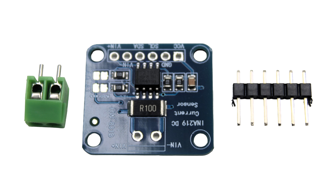
CJMCU-219 INA219 I2C Bi-directional Current/Power Supply Monitoring Module
Monitor your glove project’s LiPo battery health in real time — the INA219 tracks voltage, current, and power consumption over I2C.
9. Adding Wireless Control via Bluetooth
To make the glove truly useful as a remote controller, add an HC-05 Bluetooth module. The glove transmits gesture names or control codes wirelessly to a receiving Arduino, smartphone, or computer.
Glove (Transmitter) Side
#include <SoftwareSerial.h>
SoftwareSerial BT(10, 11);  // RX, TX for HC-05

// In setup():
BT.begin(9600);

// In loop(), after gesture identification:
if (gesture == "FORWARD") BT.print("F");
else if (gesture == "STOP")  BT.print("S");
else if (gesture == "LEFT")  BT.print("L");
else if (gesture == "RIGHT") BT.print("R");
else if (gesture == "BACK")  BT.print("B");
Robot / Receiver Side
#include <SoftwareSerial.h>
SoftwareSerial BT(10, 11);

void loop() {
  if (BT.available()) {
    char cmd = BT.read();
    switch(cmd) {
      case 'F': moveForward();  break;
      case 'B': moveBackward(); break;
      case 'L': turnLeft();     break;
      case 'R': turnRight();    break;
      case 'S': stopMotors();   break;
    }
  }
}
This two-Arduino setup allows a robot car or robotic arm to be controlled entirely through hand gestures, with no physical connection between the glove and the robot.
10. Advanced Additions: IMU and Vibration Feedback
Adding MPU6050 for Wrist Orientation
Mount an MPU6050 on the wrist of the glove to capture wrist roll, pitch, and yaw. This adds a sixth dimension of input — for example, tilting the wrist left vs right while making a “pointing” gesture can select different modes or speeds. The MPU6050 connects via I2C and can share the same Arduino as the flex sensor reading code.
Vibration Motor Haptic Feedback
Add a small coin vibration motor on the wrist. When the robot hits an obstacle or completes a specific action, the motor vibrates to give the user tactile feedback. Connect the vibration motor through a 2N2222 transistor switch (motor coil needs more current than the Arduino GPIO can supply directly).
Machine Learning Gesture Recognition
For more nuanced gesture recognition beyond simple threshold logic, collect 50–100 samples of each gesture and train a simple K-Nearest Neighbours (KNN) or decision tree model. Libraries like ArduinoML (for AVR-class microcontrollers) or TensorFlow Lite Micro (for ESP32) can run inference on-device, enabling much more complex gesture vocabularies.
11. Applications and Project Ideas
Robotic Arm Mimic
Map each finger’s bend angle directly to a servo motor angle in a robotic hand or arm. When you bend your index finger 50%, the robot’s finger bends 50%. This creates an intuitive, natural interface for teleoperation — useful in hazardous environments, remote surgery research, or factory robotics education.
Sign Language Translator
Train the glove to recognise Indian Sign Language (ISL) or American Sign Language (ASL) hand shapes. Use a text-to-speech module to speak the recognised letter or word aloud — creating a communication aid for the hearing-impaired community. This is one of the most socially impactful projects possible with flex sensors.
Drone Hand Gesture Controller
Use the glove to pilot a drone: open hand = hover, fist = descend, point forward = fly forward, wrist tilt = yaw. Transmit commands wirelessly via NRF24L01 radio module for low-latency, interference-free drone control.
VR/AR Interface Glove
Interface the glove with a PC over USB serial and use Python or Unity scripts to convert gesture data into virtual hand movements. This creates an affordable alternative to commercial VR gloves for game development, training simulations, and interactive art installations.
Musical Instrument
Map finger positions to musical notes or chords played through a buzzer or DAC. Different hand shapes produce different melodies — creating a wearable electronic musical instrument that responds to gesture rather than key presses.
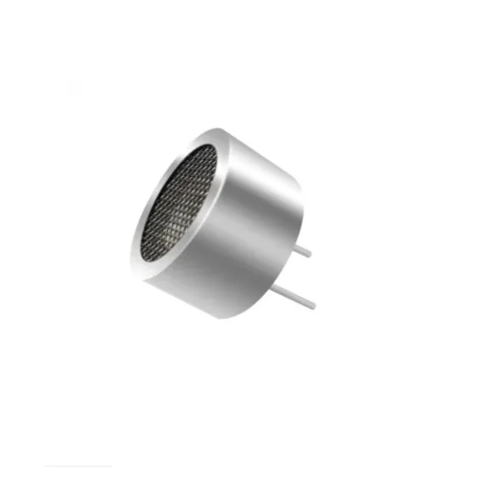
25kHz Ultrasonic Sensor Receiver T25 16mm
Add obstacle detection to your gesture-controlled robot — ultrasonic sensors provide collision avoidance while the glove handles direction commands.
12. Frequently Asked Questions
What value resistor should I use in the flex sensor voltage divider?
The ideal resistor value is roughly the geometric mean of your sensor’s minimum and maximum resistance. For a sensor with 25kΩ flat and 100kΩ fully bent, the geometric mean is √(25000 × 100000) ≈ 50kΩ. A standard 47kΩ resistor is a perfect choice. Using a value too far from this range reduces your analog reading span — for example, using a 1kΩ resistor would give almost no detectable change across the full bend range. If your sensor has different flat/bent values, recalculate accordingly.
Why do my flex sensor readings drift over time?
Resistance drift in flex sensors is normal — especially in the first 100–200 cycles on a new sensor as the conductive polymer “breaks in.” Additionally, temperature affects resistance (higher temperature = lower resistance, generally). To manage drift: (1) Break in the sensor by flexing it several hundred times before final calibration. (2) Re-calibrate occasionally, especially after the sensor has been used extensively. (3) For critical applications, include a periodic auto-calibration routine that recalibrates when the user holds their hand open flat for 3 seconds.
Can I use cheap or DIY flex sensors instead of Spectra Symbol sensors?
Yes. Inexpensive flex sensors from Chinese suppliers (often sold on Indian platforms) work for most Arduino projects, though they may have more drift, lower cycle life, and wider unit-to-unit variance. Velostat (pressure-sensitive conductive film) can also be used to make DIY flex sensors with conductive thread, though consistency is much harder to achieve. For serious projects or commercial products, genuine Spectra Symbol sensors offer much better consistency and longevity. For a learning project, budget sensors are perfectly adequate.
How many gestures can a 5-finger flex glove reliably recognise?
With binary (bent/straight) classification per finger, there are 2^5 = 32 theoretically possible gestures. In practice, some combinations are anatomically impossible (e.g., ring finger fully extended with pinky fully bent is very difficult for most people) and some are too close to others to distinguish reliably. A well-designed gesture vocabulary of 8–15 clearly distinct gestures is easily achievable. Adding wrist orientation from an IMU sensor multiplies this substantially. For a 26-letter sign language alphabet, you need finer angle resolution and possibly machine learning.
What glove material works best for a flex sensor project?
Thin cotton or nylon gloves work best. They are stretchy enough to allow sensor mounting without restricting movement, breathable for extended wear, and easy to sew sensor channels into. Avoid thick gloves (restrict finger movement), rubber gloves (flex sensors may slip), or very stretchy spandex (sensor position shifts too much). The glove should fit snugly but not tightly — too loose and sensors shift out of position, too tight and it restricts blood circulation and natural finger movement.
Conclusion
Building a flex sensor gesture recognition glove with Arduino is a rewarding project that combines electronics, mechanics, programming, and human-computer interaction. The skills you develop — reading analog sensors, calibrating transducers, writing state-machine gesture logic, and integrating wireless communication — transfer directly to professional embedded systems and IoT engineering work.
Start simple: get all five sensors reading correctly, establish calibration, and implement two or three basic gestures. Once those work reliably, layer in Bluetooth wireless, an IMU for wrist orientation, and a more sophisticated gesture vocabulary. The flex sensor glove grows naturally from a weekend prototype into a polished project worthy of an engineering exhibition or portfolio piece.


Add comment