
Darlington Transistor Pair: High Gain Switching Applications
If you’ve ever needed to control a high-current load — like a relay, solenoid, or motor — using only a tiny signal from a microcontroller, the Darlington transistor pair is your best friend. This clever two-transistor configuration multiplies current gain to extraordinary levels, allowing even a weak 5 mA GPIO pin to switch amperes of load current. In this comprehensive guide, we’ll explore exactly how Darlington pairs work, when to use them, and how to build practical switching circuits for your Arduino or Raspberry Pi projects.
What Is a Darlington Transistor Pair?
A Darlington transistor pair (also called a Darlington pair or super-beta transistor) is a compound semiconductor device formed by connecting two bipolar junction transistors (BJTs) in series so that the emitter of the first transistor drives the base of the second. The result is an equivalent transistor with an enormously high current gain — typically in the range of 1,000 to 100,000 — compared to the few hundred you’d get from a single BJT.
Sidney Darlington invented this circuit topology in 1953 while working at Bell Labs, and it has remained a fundamental building block in electronics ever since. You’ll find Darlington pairs in motor drivers, relay drivers, Darlington arrays (like the famous ULN2003), audio power amplifiers, and virtually every circuit that needs to interface a low-power control signal with a high-power load.
In India, where hobbyists commonly build projects with Arduino Uno, ESP32, and Raspberry Pi, the Darlington pair solves the very practical problem of driving 12 V relays, solenoid valves for irrigation, or DC motors directly from a 3.3 V or 5 V GPIO output that can source only 8–40 mA.
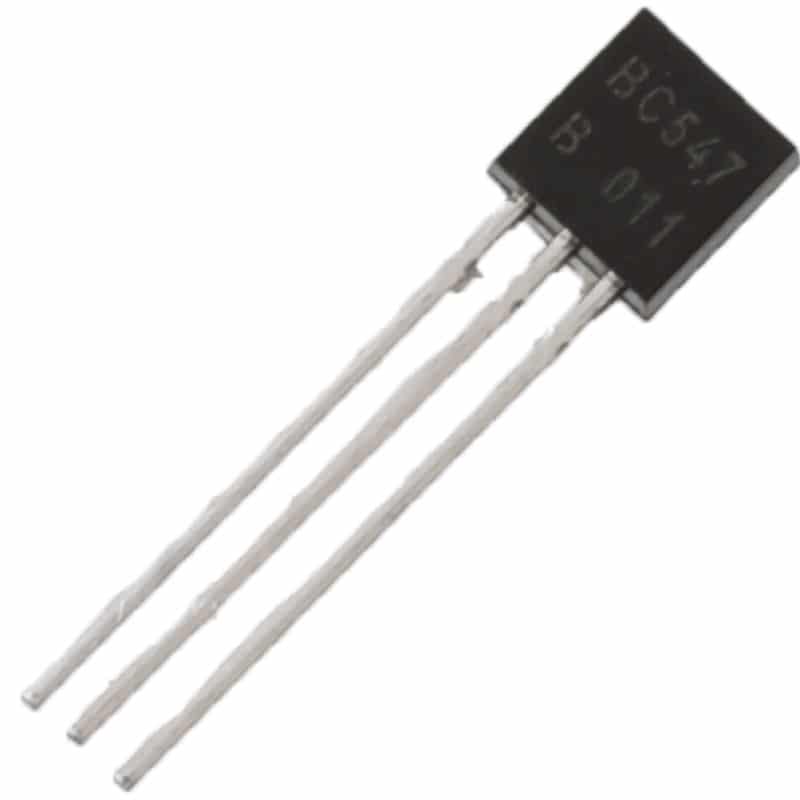
BC547 NPN 100mA Transistor TO-92 (Pack of 10)
The BC547 is perfect as the first (driver) transistor in a Darlington pair. Small, affordable, and readily available — ideal for low-signal stage amplification.
How the Darlington Configuration Works
Let’s break down the circuit step by step. In a standard NPN Darlington pair:
- Transistor Q1 (driver): A small-signal transistor whose base is connected to the input control signal. Its emitter connects directly to the base of Q2.
- Transistor Q2 (output): A power transistor capable of handling the load current. Its emitter connects to ground (in a low-side switch configuration).
- Collector connection: Both collectors are usually tied together and connected to the load.
When a small base current flows into Q1, Q1 amplifies it by its hFE1 and delivers that amplified current into the base of Q2. Q2 then amplifies again by hFE2. The overall effect is multiplicative: Ib_Q1 × hFE1 × hFE2 = Ic_Q2. This means a mere 10 µA control current could theoretically control 10 A of load current with a total gain of 1,000,000.
One important characteristic to understand: the base-emitter voltage drop of a Darlington is approximately 1.2–1.4 V (two Vbe drops stacked), compared to ~0.7 V for a single transistor. The saturation voltage (Vce_sat) is also higher — typically 0.8–1.5 V — which means more power is dissipated in the transistor when it’s fully on. For battery-powered designs, this can matter.
A free-wheeling (flyback) diode is often integrated across the collector-emitter terminals in packaged Darlington ICs. When driving inductive loads like relays and motors, always include a flyback diode to protect the transistor from voltage spikes when the inductive load is switched off.
Calculating Total Current Gain (hFE)
The total DC current gain of a Darlington pair is given by:
hFE(total) = hFE1 × hFE2 + hFE1 + hFE2
In practice, the dominant term is the product hFE1 × hFE2, so we simplify to:
hFE(total) ≈ hFE1 × hFE2
Example: If Q1 is a BC547 (hFE ≈ 200) and Q2 is a BD139 (hFE ≈ 100), the combined gain is approximately 20,000. With a 5 V GPIO pin sourcing 5 mA through a base resistor, the Darlington can theoretically switch 100 A — but real-world maximum is limited by Q2’s power dissipation and package rating.
To calculate the base resistor for a given load:
- Determine load current (IC), e.g., 500 mA relay
- Divide by total gain to get required base current: IB = IC / hFE(total)
- For reliable saturation, multiply IB by 10 (overdrive factor): IB(actual) = IC / (hFE / 10)
- RB = (Vcontrol − VBE(total)) / IB(actual)
For a 500 mA relay driven from a 5 V Arduino GPIO with a TIP122 Darlington (hFE ≈ 1000):
- IB = 500 mA / 100 = 5 mA
- RB = (5 − 1.4) / 0.005 = 720 Ω → use 680 Ω standard value
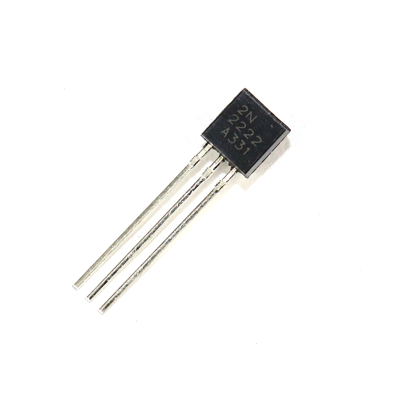
2N2222 NPN Transistor (Pack of 20)
The 2N2222 is a versatile NPN transistor that works brilliantly as either stage in a discrete Darlington pair. With hFE up to 300, it’s ideal for low-to-medium power driver circuits.
Darlington vs Single Transistor: When to Choose What
| Parameter | Single BJT | Darlington Pair |
|---|---|---|
| Current Gain (hFE) | 50–600 | 1,000–100,000+ |
| Vbe drop | ~0.7 V | ~1.2–1.4 V |
| Saturation Voltage | 0.1–0.3 V | 0.8–1.5 V |
| Switching Speed | Faster | Slower (charge storage) |
| Best For | High-speed, efficient switching | Very high gain, low Ib control |
Choose a Darlington pair when:
- Your control signal is extremely weak (microamps)
- You need to interface 3.3 V logic with 12 V/24 V loads directly
- Load current exceeds 500 mA and you want simple, reliable switching
- Using Darlington arrays like ULN2003 for multi-channel relay boards
Stick with a single transistor or MOSFET when:
- Switching frequency exceeds a few kHz (PWM motor control)
- Minimum power loss is critical (battery circuits)
- You need near-zero Vce(sat) — MOSFETs win here
Practical Switching Circuits for Indian Makers
Circuit 1: Relay Driver with BC547 + BC337 Darlington
This is the most common beginner circuit. The BC547 (driver) amplifies the Arduino GPIO signal, feeding the BC337 (output) which directly drives a 5 V relay coil drawing 80 mA.
Component list:
- Q1: BC547 NPN
- Q2: BC337 NPN
- R1: 10 kΩ (Arduino GPIO → Q1 base)
- D1: 1N4007 (flyback diode across relay coil)
- Relay: 5 V SPDT
Wire Q1 emitter → Q2 base directly. Connect both collectors to the relay coil positive terminal. Tie Q2 emitter to GND. The 10 kΩ resistor from GPIO to Q1 base gives about 0.5 mA base current — multiplied by hFE1 × hFE2 ≈ 200 × 100 = 20,000, that’s 10 A theoretical current. The relay only needs 80 mA, so it turns on rock-solid.
Circuit 2: TIP122 Single-Package Darlington for Motor Control
The TIP122 is a popular, inexpensive NPN Darlington transistor in a TO-220 package rated for 5 A, 100 V. It has an integrated flyback diode — perfect for driving DC motors up to 60 W.
Connection (low-side switch):
- Motor +12 V → Motor − → TIP122 Collector
- TIP122 Emitter → GND
- Arduino PWM → 1 kΩ → TIP122 Base
- Add 10 kΩ pull-down from Base to GND to prevent floating
With PWM at 490 Hz from Arduino (analogWrite), you can control motor speed smoothly. Note that at high PWM frequencies the Darlington may not fully switch off between pulses due to charge storage — keep PWM below 1 kHz for best results.

LCR-T4 Graphical Transistor Tester
Automatically identifies transistor pinout and measures hFE, Vbe, and leakage. Essential for verifying Darlington pair transistors before building circuits.
ULN2003 and ULN2803: Darlington Arrays Explained
When you need to drive multiple channels simultaneously — say, four stepper motor coils or eight relay channels — discrete Darlington pairs become cumbersome. That’s where Darlington array ICs shine.
ULN2003A contains seven NPN Darlington pairs in a single 16-pin DIP package. Each channel can handle 500 mA and 50 V. Input pins are compatible with both 3.3 V and 5 V logic. Common cathode flyback diodes are integrated. In India, the ULN2003 sells for around ₹10–20 per piece — incredibly cost-effective.
ULN2803A is essentially the same but with eight channels instead of seven, in an 18-pin package.
Key specifications of ULN2003:
- Input voltage: 3.3 V – 30 V (logic compatible)
- Output voltage: up to 50 V (open collector)
- Output current: 500 mA per channel (peak 600 mA)
- Built-in flyback diodes (COM pin connects to positive supply of inductive load)
- Current gain per channel: typically > 1000
Typical application: driving a 28BYJ-48 stepper motor. The stepper needs 5 V at 200 mA per coil. An Arduino can’t source this directly, but four channels of ULN2003 handle it effortlessly. This is why the 28BYJ-48 stepper almost always ships with a ULN2003-based driver board.
Tips, Tricks and Common Pitfalls
1. Always Add a Base Resistor
Never connect a GPIO pin directly to the base of a Darlington without a current-limiting resistor. Even though the base current needed is tiny, without a resistor you risk overcurrent on the GPIO. Use 1 kΩ to 10 kΩ depending on your control voltage and required base current.
2. Include a Flyback Diode for Inductive Loads
Relays, solenoids, and motors are inductive. When switched off, they generate voltage spikes that can exceed 100 V and destroy your transistor instantly. Always place a 1N4007 or 1N4148 diode in reverse across the inductive load (cathode to positive supply, anode to collector).
3. Watch Out for Thermal Runaway
Darlington pairs have two Vbe drops that increase slightly with temperature. The leakage current (Iceo) also increases with heat. For high-current applications, mount the transistor on a heatsink. A TO-220 package dissipates far more heat with a small aluminium heatsink than bare.
4. The Complementary (PNP) Darlington
A PNP Darlington pair works identically but mirrors everything. Input signal pulls the base LOW to turn the transistor ON. Useful for high-side switching where you want the load connected between transistor and positive supply. TIP127 is a popular PNP Darlington counterpart to TIP122.
5. Use Pull-Down Resistors on Input
At power-up, GPIO pins can float briefly. A 10 kΩ pull-down from the Darlington base to GND ensures the transistor stays off during microcontroller boot-up, preventing unexpected relay chatter or motor jolts.

Carbon Film Resistors (Pack of 100)
Stock up on resistors for base current limiting and pull-down applications in your Darlington switching circuits. Available in a variety of values at Zbotic.
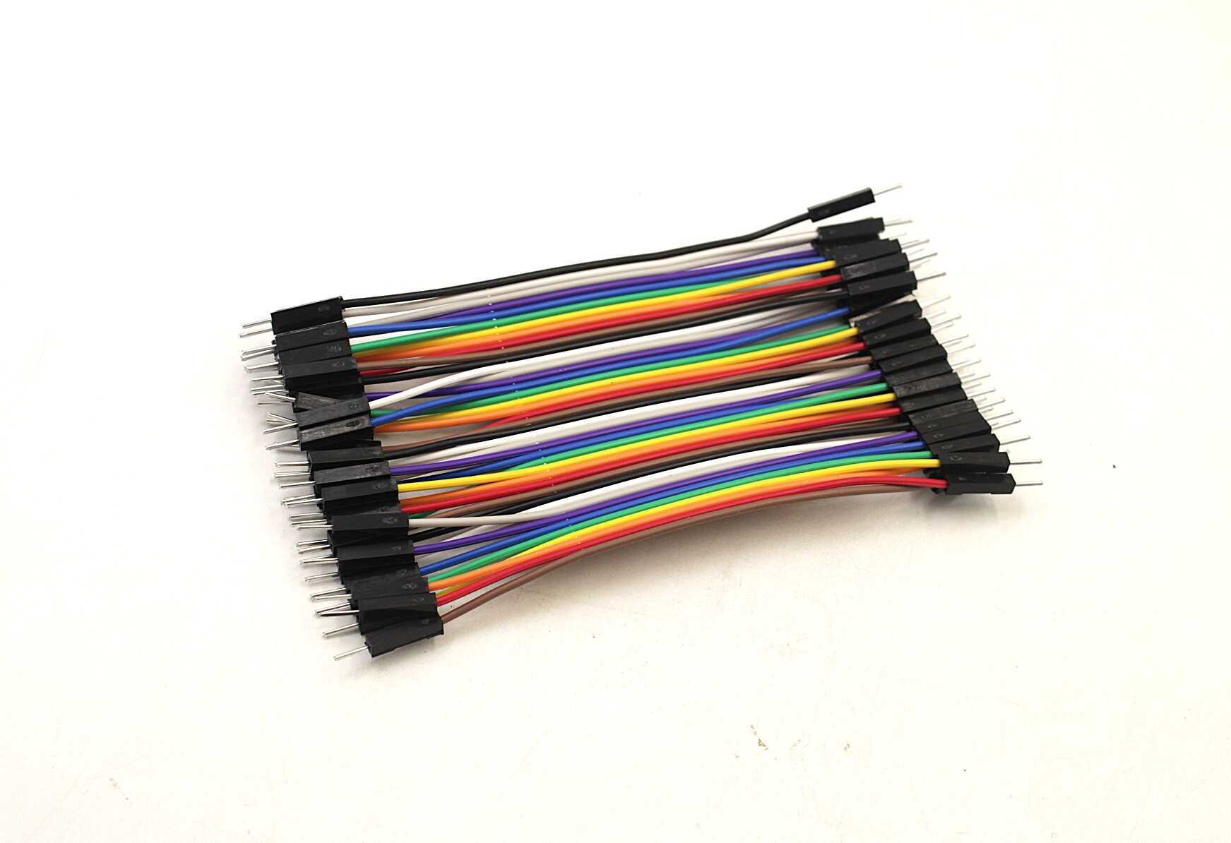
Male-to-Male Breadboard Jumper Wires 40Pcs
Essential for prototyping Darlington pair circuits on your breadboard. Short 10 cm wires keep your connections tidy and reliable during testing.
Frequently Asked Questions
Q1: Can I use a Darlington pair to switch an LED?
Technically yes, but it’s overkill for a single LED. The ~1.2 V Vbe drop plus LED forward voltage reduces the headroom available. For LEDs, a simple single transistor or even a direct GPIO connection (with resistor) is more efficient. Use Darlington pairs for high-current loads like relays, motors, and solenoids.
Q2: What is the difference between TIP120, TIP121, and TIP122?
All three are NPN Darlington transistors in TO-220 packages with integrated flyback diodes. The difference is voltage rating: TIP120 handles up to 60 V, TIP121 up to 80 V, and TIP122 up to 100 V. All three are rated for 5 A continuous collector current. For most 12 V projects, TIP120 or TIP122 are interchangeable.
Q3: Why is my Darlington transistor getting hot during switching?
The higher Vce(sat) of a Darlington (0.8–1.5 V) means more power is dissipated compared to a single BJT or MOSFET. Power dissipation = Vce(sat) × Ic. For 1 A load, that’s ~1 W of heat — enough to get very hot without a heatsink. Add an appropriate heatsink or switch to a logic-level MOSFET for high-current PWM applications.
Q4: Can I use a Darlington pair in AC switching circuits?
BJT Darlington pairs are DC devices — they cannot switch AC directly. For AC control, use a TRIAC, solid-state relay (SSR), or an optocoupler-TRIAC combination. However, you can use a Darlington to drive the gate/control circuit of an AC switching device.
Q5: How do I test if my Darlington pair is working correctly?
Use a multimeter in diode mode. You should see a forward voltage drop of approximately 1.2–1.4 V from base to emitter (two Vbe stacked). Also measure Vce(sat) under load — it should be 0.8–1.5 V when fully saturated. An LCR-T4 component tester can automatically identify the transistor type and measure hFE, which is very useful for matching pairs.
Start Building Your Darlington Circuits Today
Whether you’re driving relays, controlling motors, or building your first power electronics project, Darlington transistor pairs are an indispensable skill for every Indian electronics maker. Zbotic stocks all the transistors, resistors, and prototyping tools you need to get started.


Add comment