
Every microcontroller, UART, USB interface, and real-time clock needs a stable timing reference. That timing source is almost always either a crystal oscillator or a ceramic resonator. Both are small, look similar, and do the same fundamental job — yet they differ dramatically in accuracy, cost, size, and which applications they suit.
In this guide we compare crystal oscillator vs ceramic resonator across every dimension that matters, so you can confidently pick the right clock source for your next project.
How Crystal Oscillators and Ceramic Resonators Work
Crystal Oscillator (Quartz Crystal)
A quartz crystal exploits the piezoelectric effect. When mechanical stress is applied to a quartz crystal, it generates an electrical charge. Conversely, when an AC voltage is applied, it vibrates at a mechanically resonant frequency determined by its physical dimensions and cut angle. This resonant frequency is extraordinarily stable because it depends on the physical properties of quartz — a material that does not change significantly with temperature (especially for AT-cut crystals).
Inside a microcontroller’s crystal oscillator circuit, the crystal is connected between the XTAL1 and XTAL2 pins with two load capacitors (CL1 and CL2) to ground. The on-chip inverter amplifier, crystal, and capacitors form a feedback oscillator that oscillates at precisely the crystal’s series or parallel resonant frequency.
Ceramic Resonator
A ceramic resonator uses the same piezoelectric principle but with a ferroelectric ceramic material (usually lead zirconate titanate, PZT) instead of quartz. The ceramic material is less mechanically perfect than quartz crystal, which results in a broader resonance peak and lower Q factor — meaning the frequency is somewhat less stable.
Many ceramic resonators come as 3-pin components with built-in load capacitors, making them very easy to use — simply place between XTAL1, XTAL2, and GND with no external capacitors required.
Key Differences: Crystal vs Ceramic
| Property | Crystal Oscillator | Ceramic Resonator |
|---|---|---|
| Frequency accuracy | ±10–50 ppm | ±0.5–1% |
| Temp stability | Excellent (AT-cut: ±10 ppm over −40 to +85°C) | Moderate (±0.3–0.5% typical) |
| Q factor | 10,000–1,000,000 | 500–5,000 |
| External caps needed | Yes (2 load caps) | No (built-in on 3-pin types) |
| Startup time | Slower (1–10 ms) | Faster (300 µs–1 ms) |
| Cost | Higher | Lower |
| Best for | USB, UART, RTC, precision timing | Low-cost MCU clocking, tolerant protocols |
Frequency Accuracy and Stability
ppm Explained
ppm (parts per million) is the standard unit for crystal accuracy. 1 ppm means the frequency may deviate by 1 Hz for every 1,000,000 Hz of nominal frequency. For a 16 MHz crystal:
- ±50 ppm = ±800 Hz variation → error of 0.8 µs per second
- ±10 ppm = ±160 Hz variation → error of 0.16 µs per second
Ceramic Resonators: ±0.5% Means What?
0.5% = 5,000 ppm. On a 16 MHz resonator, that’s ±80,000 Hz potential deviation. For a UART running at 9600 baud, the bit period is 104 µs. UART can tolerate roughly ±3–4% timing error. A ceramic resonator’s ±0.5% is within this margin — which is why ceramic resonators work fine for UART, SPI, and I2C in most cases.
However, for USB Full-Speed, the spec allows only ±2,500 ppm (±0.25%). A standard ceramic resonator exceeding ±0.5% will fail USB enumeration. You must use a crystal for USB.
Temperature Effects
Quartz crystals — particularly AT-cut — have a very flat frequency-vs-temperature curve in the −40°C to +85°C range, typically staying within ±10–30 ppm. Ceramic resonators are far more temperature-sensitive, drifting several thousand ppm from cold startup to operating temperature. For outdoor equipment, industrial control, or anything requiring consistent timing across temperatures, use a crystal.
Load Capacitance Requirements
Crystals Need Precise Load Capacitors
Every crystal datasheet specifies a load capacitance (CL) — typically 8 pF, 12 pF, or 18 pF. You must provide two external capacitors (CL1 and CL2) to ground, with each value chosen so the series combination equals CL:
CL = (CL1 × CL2) / (CL1 + CL2) + Cstray
For CL = 12 pF and Cstray ≈ 3 pF: use CL1 = CL2 = 18 pF
Using wrong capacitor values shifts the oscillation frequency. It is a common mistake that makes a 16 MHz crystal run at 15.998 or 16.002 MHz — which matters for UART, USB, and real-time clocks.
Ceramic Resonators: Built-In Caps
3-pin ceramic resonators integrate the load capacitors inside the package. Simply connect XTAL1 → pin 1, GND → pin 2 (center), XTAL2 → pin 3. No external capacitors needed, which reduces component count, bill of materials cost, and PCB footprint. This is a genuine practical advantage in consumer and cost-sensitive designs.
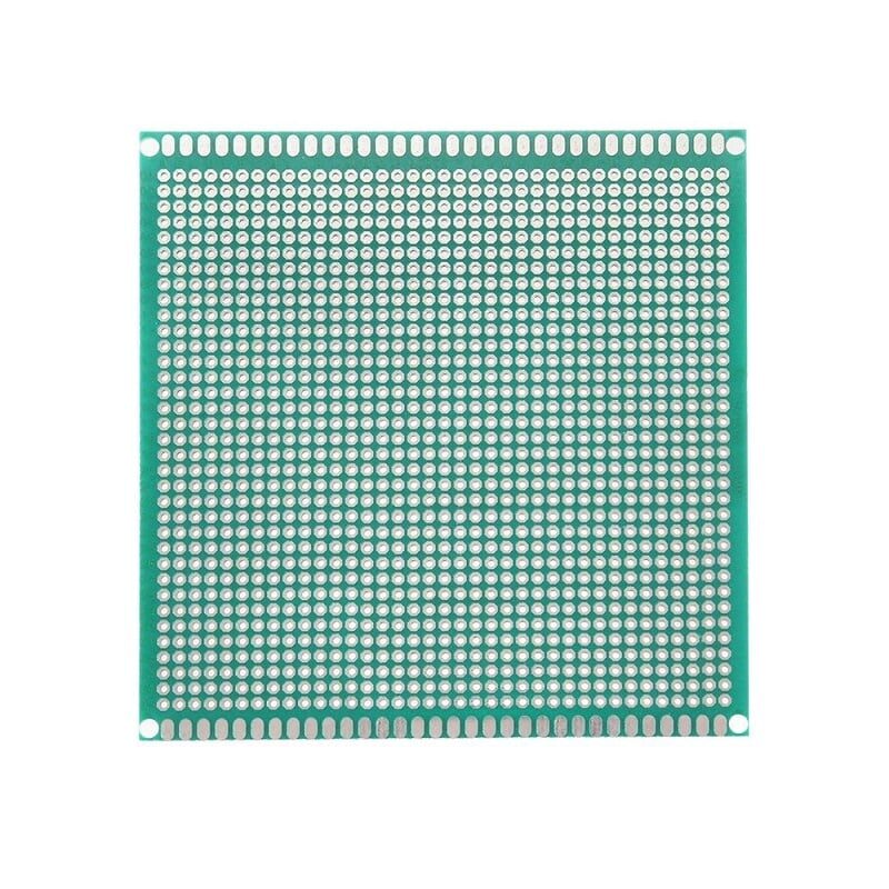
10x10cm Universal PCB Prototype Board
Perfect for building crystal oscillator circuits and clock source experiments before committing to a custom PCB layout.
Startup Time
Ceramic resonators start up faster than quartz crystals, typically reaching stable oscillation in 300 µs to 1 ms versus 1–10 ms for a crystal. This matters in applications that wake from deep sleep frequently (IoT battery devices), where every millisecond of startup time costs energy. For always-on or rarely-sleeping systems, startup time is irrelevant.
Cost, Size, and Availability
Ceramic resonators are cheaper than crystals — typically by 30–60%. They also require fewer external components (no load caps) and are available in smaller SMD packages. For high-volume consumer products where cost and PCB area are critical, ceramic resonators win on economics.
Quartz crystals are widely available in standard frequencies (8, 12, 16, 20 MHz for microcontrollers; 32.768 kHz for RTCs) and SMD packages. They are not expensive in hobbyist quantities but do require load capacitors, adding 2 components to the BOM.
Which Should You Choose?
Always Use a Crystal When:
- Your design includes USB (Full-Speed or High-Speed) — the ±2500 ppm tolerance demands crystal accuracy
- You need a Real-Time Clock (RTC) — a 1,000 ppm error means 86 seconds of drift per day
- You are implementing Bluetooth or Wi-Fi — RF protocols require extremely accurate clock references
- You are using CAN bus at high bit rates — bit timing tolerance is strict
- Your product operates over a wide temperature range (industrial/outdoor)
- You need precise baud rate generation for multiple UARTs at high speed
A Ceramic Resonator Is Fine When:
- You are building a basic Arduino/MCU project with SPI, I2C, or low-speed UART
- Cost and PCB space are critical constraints
- The operating temperature range is narrow (room temperature only)
- Timing tolerances are relaxed (controlling LEDs, reading sensors, simple displays)
- The microcontroller has its own internal oscillator and the resonator is just for better accuracy than the internal RC
Using a Crystal with a Microcontroller
- Check the datasheet for the crystal load capacitance (CL) spec — typically 8–18 pF for microcontrollers.
- Calculate external capacitor values: CL1 = CL2 = 2 × (CL − Cstray). Typical Cstray ≈ 2–5 pF for through-hole, 1–3 pF for SMD.
- Choose an AT-cut crystal for the right frequency. Verify maximum drive level matches your MCU’s oscillator output.
- Keep traces short and away from noisy signals. Wrap a ground guard ring around the crystal and XTAL traces on the PCB.
- Do not connect probe tips to XTAL pins while measuring — even 10 pF from a scope probe will shift frequency and may kill oscillation.

0 Ohm 0.25W Carbon Film Resistor (Pack of 100)
Useful as jumper links and for managing crystal oscillator circuit layout during prototyping on perfboards.
Using a Ceramic Resonator
- Connect pin 1 to XTAL1, center pin (2) to GND, pin 3 to XTAL2.
- No external load capacitors are needed for 3-pin resonators.
- Configure the microcontroller fuse bits or firmware clock settings to select the external crystal/resonator oscillator.
- Note: 2-pin ceramic resonators (without built-in caps) still need external load capacitors — check the package pinout carefully.
Real-Time Clocks and 32.768 kHz Crystals
The 32.768 kHz frequency is the universal standard for RTC crystals. Why 32,768? Because 32,768 = 2¹⁵. Divide it by 2 fifteen times and you get exactly 1 Hz — a perfect seconds tick with simple binary dividers. RTCs (DS3231, DS1307, PCF8523) all use external or internal 32.768 kHz crystals.
For RTC applications, accuracy matters a lot. A 20 ppm crystal loses/gains ±1.7 seconds per day. The DS3231 has a temperature-compensated crystal internally and achieves ±2 ppm (±0.17 seconds/day) — impressive. If you are building a standalone RTC with a basic DS1307, use the best 32.768 kHz crystal you can find with lowest specified frequency tolerance.
Crystal Oscillator Modules (TCXO, OCXO)
For even higher accuracy, complete oscillator modules are available:
- Crystal Oscillator (XO): A 4-pin module with crystal and oscillator circuit built in. Output is a CMOS clock signal, no external components needed. Common frequencies: 1–200 MHz.
- TCXO (Temperature Compensated Crystal Oscillator): Adds temperature compensation circuitry. Achieves ±0.5–2.5 ppm across temperature. Used in GPS modules, cellular modems.
- OCXO (Oven Controlled Crystal Oscillator): The crystal is kept in a temperature-controlled oven. Achieves ±0.001–0.01 ppm accuracy. Used in test equipment and professional frequency standards. Expensive and power-hungry.
Frequently Asked Questions
Can I use a ceramic resonator instead of a crystal on Arduino?
Yes, for most Arduino sketches. The Arduino Uno uses a 16 MHz ceramic resonator on some clone boards and it works fine for GPIO, SPI, I2C, and standard UART. However, if you are building something that requires USB (like the Arduino Leonardo’s ATmega32U4), you must use a crystal — USB requires ±2500 ppm which exceeds ceramic resonator specs.
What is the ppm of a typical quartz crystal?
Consumer through-hole crystals are typically rated ±20–50 ppm initial tolerance. Higher-quality SMD crystals are ±10 ppm. AT-cut crystals maintain this stability over temperature. For comparison, a microcontroller’s internal RC oscillator is typically ±1–3% (10,000–30,000 ppm) from factory — much worse than even a ceramic resonator.
Why does my oscillator not start up?
Common causes: wrong load capacitors (too high or too low), excessive PCB trace length or capacitance, inappropriate MCU oscillator gain setting (low/high gain mode), or a defective crystal. Check the datasheet for the recommended external capacitor values and oscillator gain configuration bits.
Can I run a microcontroller without a crystal?
Yes. Most modern microcontrollers (ATmega328P, ESP32, STM32, RP2040) include an internal RC oscillator. It is typically ±1% accurate after factory calibration — fine for non-communication tasks. The ESP32’s internal oscillator is automatically calibrated against an external 40 MHz crystal if one is connected.
What frequency crystal does Arduino Uno use?
The official Arduino Uno uses a 16 MHz quartz crystal (or some clones use a 16 MHz ceramic resonator). The clock feeds directly into the ATmega328P XTAL1/XTAL2 pins with 22 pF load capacitors.
Building precision timing circuits? Zbotic.in stocks all the passive components you need — capacitors, resistors, PCB boards, and more. Shop now at zbotic.in for fast delivery across India.


Add comment