
The counter IC 4017 circuit is one of the most satisfying and beginner-friendly experiments in digital electronics — a handful of components, a single IC, and you have a 10-step sequencer that can drive LED chasers, control relay sequences, generate arbitrary waveforms, and divide frequencies. The CD4017 Johnson decade counter has been a staple in electronics labs and maker projects for decades, and for good reason: it’s cheap (under ₹20), extremely easy to use, and opens the door to understanding how digital counters and sequencers work in everything from washing machines to industrial automation systems.
Table of Contents
- How Digital Counters Work
- CD4017 Johnson Decade Counter Overview
- Classic LED Chaser Circuit
- 74HC390 Dual Decade Counter
- Frequency Divider Applications
- Advanced Sequencer Projects
- Troubleshooting Counter Circuits
- Frequently Asked Questions
How Digital Counters Work
A digital counter is a sequential logic circuit that moves through a predefined sequence of states, advancing one step each time it receives a clock pulse. Unlike combinational logic where the output depends only on current inputs, counters are sequential — they remember their current state and transition to the next state based on both the clock and the stored state.
The two fundamental types of counters are:
- Binary counters: Count in binary (0000→0001→0010…→1111), typically implemented with cascaded flip-flops. The 74HC390 is a dual BCD ripple counter in this category.
- Ring/Johnson counters: Shift a single active bit (or its complement) through a chain of flip-flops. The CD4017 is a Johnson counter that produces one-hot outputs (only one output HIGH at a time) — ideal for sequencers.
Counters are characterized by their modulus — the number of states in their sequence. A modulo-10 (decade) counter like the 4017 has 10 states. By connecting the RESET pin to one of the count outputs, you can create counters with any modulus from 2 to 10.
CD4017 Johnson Decade Counter Overview
The CD4017 (also available as HEF4017, MC14017) is a 16-pin CMOS decade counter with 10 decoded one-hot outputs. It operates from 3V to 15V and can drive LEDs directly without external transistors.
Pinout (DIP-16):
- Pins 3,2,4,7,10,1,5,6,9,11: Outputs Q0–Q9 (one goes HIGH at a time)
- Pin 12: CARRY OUT — goes HIGH for counts 0–4, LOW for 5–9 (50% duty cycle)
- Pin 14: CLOCK — count advances on rising edge
- Pin 13: CLOCK ENABLE (CE) — LOW enables counting, HIGH freezes
- Pin 15: RESET — HIGH resets counter to Q0 immediately (asynchronous)
- Pin 8: VSS (GND)
- Pin 16: VDD (power, 3–15V)
Key features:
- One-hot decoded outputs: Q0 through Q9 go HIGH one at a time in sequence
- Can sink/source 15mA per output at 10V (directly drives LEDs with series resistor)
- Carry Out for cascading multiple 4017s to create counters with more steps
- Wide supply range (3–15V) — works with both 5V Arduino projects and 12V standalone circuits
Classic LED Chaser Circuit
The 4017 LED chaser is the “Hello World” of sequential electronics. It creates a running light effect — one LED on at a time, cycling through all 10 in sequence. Here’s how to build it:
Components:
- CD4017 IC
- NE555 Timer IC (for clock generation)
- 10 x LEDs (any colour)
- 10 x 470Ω resistors (current limiters for LEDs)
- 10µF electrolytic capacitor (for 555 timing)
- 10kΩ + 100kΩ resistors (for 555 timing)
- 100nF ceramic capacitor (decoupling)
- 5V or 9V supply
NE555 astable oscillator (clock source):
- Pin 1 (GND) → GND
- Pin 2 (TRIGGER) → Pin 6 (THRESHOLD), connected together
- Pin 3 (OUTPUT) → CD4017 Pin 14 (CLOCK)
- Pin 4 (RESET) → VCC (always enabled)
- Pin 5 (CONTROL) → 100nF cap to GND
- Pin 6 (THRESHOLD) → 10µF cap to GND
- Pin 7 (DISCHARGE) → 100kΩ → Pin 6, also 10kΩ → VCC
- Pin 8 (VCC) → 5V
This gives approximately f = 1.44 / ((10kΩ + 200kΩ) × 10µF) ≈ 0.68 Hz — one LED advancing roughly every 1.5 seconds. Adjust the 100kΩ resistor (or replace it with a potentiometer) to change the chase speed.
CD4017 connections:
- Pin 16 (VDD) → VCC
- Pin 8 (VSS) → GND
- Pin 13 (CE) → GND (always counting)
- Pin 15 (RESET) → GND (free running 0–9)
- Pins Q0–Q9 → 470Ω resistor → LED anode, LED cathode → GND
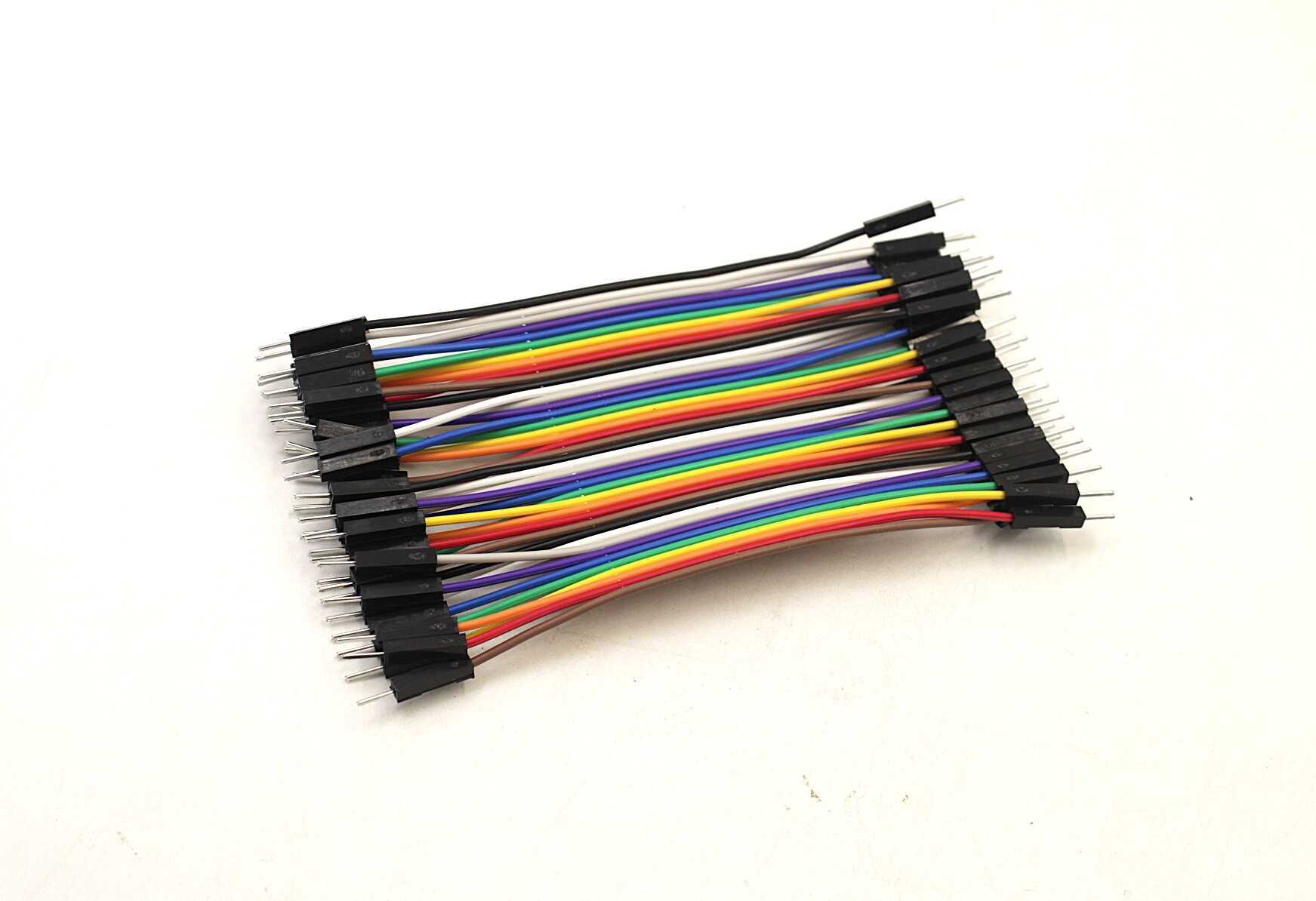
10CM Male To Male Breadboard Jumper Wires 2.54MM – 40Pcs
Essential jumper wires for building your CD4017 LED chaser circuit on a breadboard. Pack of 40 colour-coded wires — enough for complex IC circuits.
74HC390 Dual Decade Counter
The 74HC390 is a completely different animal from the 4017. It contains two independent BCD (Binary Coded Decimal) ripple counters, each capable of divide-by-2 and divide-by-5 operations. By cascading the ÷2 and ÷5 sections, you get a ÷10 BCD counter with 4-bit binary output.
Pinout (DIP-16), one counter section:
- CKA: Clock input for ÷2 section
- QA: Output of ÷2 (1-bit)
- CKB: Clock input for ÷5 section (connect QA here for ÷10 BCD mode)
- QB, QC, QD: Outputs of ÷5 (3-bit binary for counts 0–4)
- MR: Master Reset (active HIGH)
The 74HC390 outputs 4-bit BCD (0000–1001), making it ideal for driving 7-segment displays via a BCD-to-7-segment decoder like the 74HC4511. This is the classic “digital counter display” circuit used in lab frequency counters, timers, and event counters.
74HC390 vs CD4017 comparison:
| Feature | CD4017 | 74HC390 |
|---|---|---|
| Output type | One-hot (10 outputs) | BCD binary (4 outputs) |
| Best for | LED sequencers, direct control | Display driving, frequency division |
| Supply voltage | 3–15V | 2–6V |
| Max clock frequency | ~6 MHz at 10V | ~50 MHz at 5V |
| Decoding needed for 7-seg | Not directly compatible | Direct via 74HC4511 |
Frequency Divider Applications
Both the CD4017 and 74HC390 excel at frequency division — taking a fast clock and producing a slower output. This is essential for generating precise timing signals from a crystal oscillator.
Dividing with CD4017:
Connect the RESET pin to the desired output pin. If you connect RESET to Q5, the counter resets after reaching Q4, giving a ÷5 divider. Connect RESET to Q3 for ÷3, Q7 for ÷7, etc. The CARRY OUT pin always gives ÷2 regardless of reset setting.
Creating a divide-by-100 counter with two 74HC390s:
- IC1 configured as ÷10 BCD: feed your input clock to CKA1, connect QA1 to CKB1
- QD1 (most significant output of first IC) feeds CKA2 of IC2
- Connect QA2 to CKB2 for the second ÷10 stage
- QD2 of IC2 gives output at 1/100th the input frequency
For example, feeding a 1kHz signal from a 555 timer → ÷100 → 10Hz output, which you can use to blink an LED exactly once every 100ms — a precise heartbeat for your circuit without a microcontroller.

0.1/100nF – TH-Multilayer Ceramic Capacitor (Pack of 50)
Decoupling capacitors for CMOS counter ICs. Every counter IC circuit needs 100nF bypass caps — this pack of 50 has you covered for many projects.
Advanced Sequencer Projects
1. Relay Sequencer (Irrigation Pump Controller)
Use the CD4017 with 5 reed relays to control 5 irrigation zones, each running for a set time before advancing to the next. Clock the 4017 from a 555 timer set to the desired zone duration (e.g., 15 minutes = extremely slow clock). Connect RESET to Q5 for a 5-zone cycle. Cost: under ₹300 for the complete circuit, versus ₹5000+ for a commercial irrigation timer.
2. DTMF Tone Sequencer
Combine a 4017 with a DTMF generator IC (like the MT8870 or HT9200) to generate sequential dial tones for automated phone systems or test equipment. Each 4017 output enables a different tone combination.
3. Binary Pattern Generator
Use the 74HC390 to generate repeating binary patterns for testing digital circuits. By selectively ANDing and ORing the BCD outputs, you can create custom binary sequences without a microcontroller — useful for testing shift registers, decoders, and display drivers.
4. PWM Dimmer with Counter
Feed the carry output of a 4017 (÷10) to the input of another 4017. Use a binary comparator to compare the cascade counter output with a set value from DIP switches. This creates a simple digital PWM with 100 discrete brightness levels — no Arduino needed.
5. Running Text Display
Cascade four 4017s to create a 40-step sequencer. Each step enables one column of a dot-matrix LED display, cycling through characters stored in a ROM or EEPROM. A classic project for engineering students learning digital design concepts.
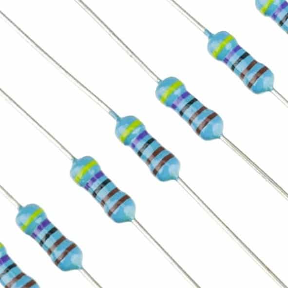
1.5 Ohm [0.25W] 1/4W Metal Film Resistor MFR (Pack of 100)
Precision metal film resistors for timing circuits and current limiting. Lower tolerance than carbon film — better for frequency-critical counter applications.
Troubleshooting Counter Circuits
Problem: Counter skips steps or misses counts
Usually caused by clock signal noise or a missing decoupling capacitor. Add a 100nF ceramic cap between VDD and VSS right at the IC. Also check that the clock signal has clean edges — use a Schmitt trigger buffer (74HC14) between the 555 and the 4017 clock input.
Problem: Counter resets spontaneously
Check the RESET pin — it must be connected to GND (or LOW) for normal operation. If left floating, CMOS inputs pick up stray static charge and may trigger random resets. Always tie unused inputs to a defined logic level.
Problem: Only first 2-3 outputs light up
The 4017 CARRY OUT pin might be accidentally connected to the RESET pin. Also check if RESET is tied to Q3 or Q4 inadvertently (a common breadboard misrouting).
Problem: Counter runs too fast or erratically with 555
Check the 555 timing capacitor — electrolytic capacitors have high tolerance (±20%) and can vary significantly. The capacitor must be connected with correct polarity. Also verify Pin 5 (CONTROL) has its 100nF noise bypass cap to GND.
Problem: LEDs dim at all outputs simultaneously
The 4017 can only source ~15mA per output at 10V. If you have high-current LEDs or more than 10 LEDs per output (for higher voltage operation), use a transistor driver. BC547 or 2N2222 NPN transistors work well for this.
Frequently Asked Questions
Q: Can CD4017 be interfaced directly with Arduino?
Yes, but carefully. At 5V supply (matching Arduino), the 4017 inputs are 5V logic compatible. Use a 5V supply for the 4017 VDD and connect Arduino’s digital output to Pin 14 (CLOCK). Do not run the 4017 at 12V when interfacing with Arduino — the output HIGH of 12V will damage Arduino GPIO pins. Alternatively, use a level shifter and run the 4017 at any voltage independently.
Q: How do I make a 4017 count up to a number other than 10?
Connect the output you want to reset at to the RESET pin (Pin 15). For example: wire Q7 to RESET → counter sequences 0,1,2,3,4,5,6, then resets. This gives you divide-by-7. The RESET is asynchronous and very fast — you see a momentary glitch on the reset output, but it’s so brief it’s usually invisible to LEDs.
Q: What is the difference between ripple counter and synchronous counter?
In a ripple (asynchronous) counter like the 74HC390, the clock propagates through each flip-flop in sequence, creating a small time delay (ripple) between the MSB and LSB changing. In a synchronous counter, all flip-flops share the same clock and switch simultaneously. Ripple counters are simpler and use less hardware; synchronous counters are faster and glitch-free at high speeds. For applications below 1MHz, ripple counters work fine.
Q: Can I use 4017 for a musical note sequencer?
Absolutely — this is one of the most popular music/electronics crossover projects. Each output of the 4017 can enable a different RC timing network in a 555 astable circuit, producing a different frequency. As the 4017 steps through its sequence, the 555 plays different notes. You get a simple 10-note melody generator with just two ICs and a handful of passive components — under ₹100 total.
Q: Is the 74HC390 compatible with TTL logic?
The 74HC390 has TTL-compatible inputs (accepts TTL HIGH levels of 2V+). However, the output may not directly drive all TTL loads due to the CMOS output characteristics. For driving TTL circuits from 74HC390, ensure VCC is 5V and the load current is within the 74HC390’s drive capability (~25mA per output). Alternatively, use the 74HCT390, which has guaranteed TTL input compatibility.
Ready to build your sequencer? Find all the components you need — counter ICs, resistors, capacitors, jumper wires, and more at Zbotic Electronics Basics. We stock genuine components with fast delivery across India. Start your counter project today!


Add comment