
If you have ever connected two circuits together and ended up with strange behaviour, flickering outputs, or outright component failure, the culprit is very often a missing or improper common ground in electronics. Ground is the invisible backbone of every circuit — from a simple LED blinker to a complex Arduino-based IoT device. Yet it is one of the most misunderstood concepts for beginners. In this guide, we will break down what common ground really means, why every circuit needs it, and how you can implement it correctly in your projects.
Table of Contents
- What Is Ground in Electronics?
- Why Do Circuits Need a Common Ground?
- Types of Ground: Signal, Power, and Earth
- Connecting Multiple Power Supplies: The Common Ground Rule
- Ground in Arduino and Microcontroller Projects
- Ground Loops and How to Avoid Them
- Recommended Products for Grounding Your Projects
- Frequently Asked Questions
What Is Ground in Electronics?
In electronics, ground (abbreviated GND) is the reference point from which all voltages in a circuit are measured. It is the zero-volt baseline. Think of it like sea level for elevation — every voltage measurement is meaningful only when you know the reference it is measured from.
Ground is not always connected to the physical Earth (though in mains-powered appliances it often is). In battery-powered circuits, ground is simply the negative terminal of the battery. In a 5V Arduino circuit, ground is the negative rail of your power supply, and every voltage — 3.3V, 5V, sensor output — is measured relative to that rail.
The symbol for ground appears in three common forms on schematics:
- Earth ground (three horizontal lines tapering to a point) — used for chassis/mains earth connections
- Chassis ground (three diagonal lines) — connected to the metal body of equipment
- Signal/digital ground (three horizontal lines of equal width) — the reference for signal circuits
For most hobbyist projects in India — Arduino, Raspberry Pi, sensor modules — you will deal primarily with signal/digital ground. But understanding all three helps you read datasheets and schematics without confusion.
Why Do Circuits Need a Common Ground?
Here is the core principle: current must always have a return path. Every electron that leaves a power supply’s positive terminal must return to its negative terminal (ground). If you connect two separate circuits without linking their ground rails, there is no shared reference — and no complete return path for current.
Imagine you have a 5V Arduino and a 12V motor driver. The Arduino sends a PWM signal to the motor driver’s input pin. The motor driver sees this signal relative to its own ground. If the Arduino’s GND and the motor driver’s GND are not connected together, the signal voltage means nothing to the motor driver — it has no common reference. The result: erratic motor behaviour, potential damage to the Arduino’s GPIO pin, or no response at all.
This shared reference is what we call the common ground. It is a single GND rail (or node) that all components in a system share, ensuring every voltage measurement and signal is interpreted consistently by every component.
Key reasons common ground matters:
- Voltage references align — a 3.3V logic signal from a sensor is correctly interpreted as 3.3V by the microcontroller because both share the same GND reference.
- Current return paths are complete — no floating nodes, no unexpected voltage offsets.
- Noise immunity improves — a well-implemented common ground reduces electromagnetic interference (EMI) between sub-circuits.
- Protection — prevents voltage differentials between ground planes that can destroy ICs and communication interfaces like I2C and SPI.

10CM Male To Female Breadboard Jumper Wires 2.54MM – 40Pcs
Essential for connecting GND rails between modules on a breadboard. These 40-piece M-F jumper wires make it easy to share a common ground across your Arduino, sensor modules, and motor drivers.
Types of Ground: Signal, Power, and Earth
Not all grounds are the same. In a well-designed electronics project, you may have multiple types of ground that are eventually tied together — but managed separately for performance and safety.
Signal Ground (SGND)
Signal ground is the reference for analog and digital signal circuits. It must be as clean and noise-free as possible. Any voltage fluctuation on signal ground appears as noise at the input of your ADC, op-amp, or microcontroller. Keep signal ground traces short and wide, and route them away from high-current paths.
Power Ground (PGND)
Power ground carries the return current for high-power components: motors, relays, high-wattage LEDs, and SMPS converters. Because large currents create voltage drops even in low-resistance traces (due to V = I × R), you do not want power return currents flowing through your signal ground. On PCBs, power ground and signal ground are often separate planes that meet at a single star point.
Earth / Chassis Ground
For mains-connected appliances in India (operating at 230V AC, 50Hz), the earth ground is connected to the physical earth via the green/yellow wire in a three-pin plug. This is a safety ground — not intended to carry signal current — and it protects users from electric shock if a fault connects the live wire to the chassis.
In hobbyist projects, you will rarely connect your digital/signal ground to earth, unless you are building mains-powered equipment. Always exercise caution with mains voltages.
Connecting Multiple Power Supplies: The Common Ground Rule
One of the most common mistakes Indian makers make when stepping up from single-board projects to multi-module systems is forgetting to tie grounds together when using multiple power supplies. Here is what happens:
Suppose you are powering an Arduino from a USB cable (5V via PC) and also powering a 12V motor driver from a separate DC adapter. The Arduino outputs a PWM signal to the motor driver’s enable pin. Without a common GND wire between the Arduino’s GND and the motor driver’s GND, the PWM signal has no return path relative to the motor driver — the motor may not respond, or worse, excessive current flows through the signal line.
The fix is simple: run a wire from the Arduino GND pin to the GND terminal of the motor driver. Now both power supplies share a common reference node. The PWM signal is correctly interpreted, current returns properly, and your motor responds predictably.
Important rule: when combining power supplies of different voltages, always connect their negative/GND terminals together (unless galvanic isolation is intentionally required, as in isolated DC-DC converters). Never float any ground relative to another in an interconnected system.

10CM Female To Female Breadboard Jumper Wires 2.54MM – 40Pcs
Perfect for connecting GND pins between modules that use male pin headers. A pack of 40 F-F jumper wires ensures you never run out when wiring up multi-module projects.
Ground in Arduino and Microcontroller Projects
The Arduino is the go-to prototyping platform for makers across India. Here is how common ground works in typical Arduino scenarios:
Powering from USB
When Arduino is powered via USB, the GND pin on the board is connected to the USB ground (PC chassis ground via USB cable). All sensors and modules sharing this GND are referenced to this point. This is perfectly fine for bench prototyping.
Powering from External DC Adapter
When using a 12V DC adapter with a barrel jack, the Arduino’s VIN pin accepts the 12V and its onboard regulator produces 5V. The GND pin is now referenced to the adapter’s negative terminal. If you add another module powered from the same adapter, connect its GND to the Arduino’s GND — same rail, no problem. If the second module has its own separate adapter, you must still tie the GNDs together.
I2C and SPI Multi-Device Projects
I2C uses SDA and SCL lines with pull-up resistors. The logic levels on these lines are measured relative to GND. If you have an OLED display, a temperature sensor, and a real-time clock all on the same I2C bus, all three must share GND with the Arduino. Missing even one GND connection will corrupt the entire bus.
Analog Sensors
Analog sensors like the LM35 temperature sensor output a voltage proportional to temperature. This voltage is meaningless unless the Arduino’s AGND (analog ground, usually the same as GND on standard boards) is connected to the sensor’s GND. A floating sensor ground gives random ADC readings — a very common debugging headache!

LM35 Temperature Sensors
A classic analog temperature sensor ideal for learning about voltage references and common ground. Pair with Arduino for temperature monitoring projects — remember to tie GND correctly for accurate readings!
Ground Loops and How to Avoid Them
A ground loop occurs when there are multiple conductive paths between two grounds, and those paths have different impedances or pick up different levels of interference. The result is a small voltage differential between two points that should be at the same potential — this manifests as hum, noise, or measurement errors.
Ground loops are common in audio systems (the classic 50Hz hum when connecting a PC to speakers), industrial sensor systems, and any setup that spans large physical distances.
How to avoid ground loops in your projects:
- Use a single-point (star) ground — all ground connections meet at one central point rather than forming a chain.
- Keep ground traces short and wide on PCBs to minimise impedance differences.
- Use a solid ground plane on multi-layer PCBs — a copper pour on the bottom layer that all GND vias connect to.
- Separate analog and digital grounds on mixed-signal boards, connecting them at a single point near the power supply.
- Use optocouplers or isolation amplifiers when connecting circuits that are physically far apart or powered by separate mains outlets.
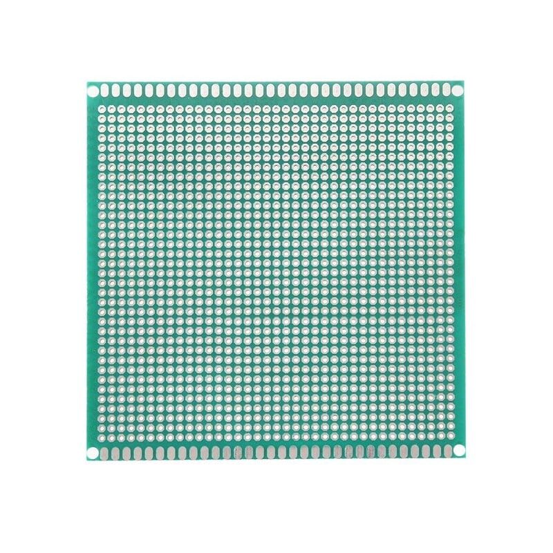
10 x 10 cm Universal PCB Prototype Board Single-Sided
Move your breadboard circuits to a permanent prototype PCB. A dedicated GND rail on this board ensures a clean common ground for all your components — ideal for finalising projects before custom PCB fabrication.
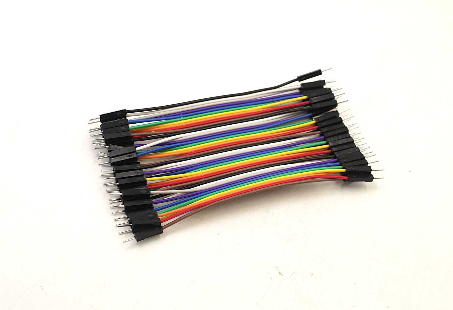
10CM Male To Male Breadboard Jumper Wires 2.54MM – 40Pcs
Stock your workbench with M-M jumper wires to build reliable GND rails on breadboards. Use the black wires as a convention for ground connections to keep your wiring neat and easy to debug.
Frequently Asked Questions
Q: Can I use any wire colour for ground?
Technically yes, but the universal convention is black for ground (and red for positive). Following this convention makes debugging far easier — you and others can immediately identify ground connections at a glance.
Q: Do I need to connect GND if I am using the same battery for all components?
If all components share the exact same battery with a common negative terminal (e.g., on the same breadboard power rail), they already share a common ground. However, if any module has its own separate power source, you must explicitly connect the GNDs.
Q: What happens if I accidentally create multiple ground connections between two circuits?
This can create a ground loop, resulting in noise or measurement errors. In low-frequency digital circuits this is often harmless, but in analog and audio circuits it causes audible hum or inaccurate readings. Use star grounding to keep a single path.
Q: Is ground the same as neutral in Indian AC wiring?
No. In Indian 230V AC wiring, neutral is the return current conductor (white/blue wire) and earth/ground is the safety conductor (green/yellow wire). In normal operation, the earth wire carries no current — it only activates if there is a fault. Never confuse neutral and earth in mains circuits.
Q: My Arduino project works fine on a breadboard but fails when I put it in an enclosure — why?
A common cause is a floating ground — a GND wire that was connected on the breadboard but got disconnected inside the enclosure. Double-check all GND connections. Also check if the metal enclosure is accidentally touching circuit nodes, creating an unintended ground path.
Ready to build reliable circuits? Browse the full range of jumper wires, prototype PCBs, resistors, and capacitors at Zbotic Electronics Components. Fast shipping across India — from Mumbai to Mangalore, your parts arrive ready to prototype!


Add comment