
Build a Simple DC Power Supply: Transformer to 5V DC
If you want to build a simple DC power supply, you’ve come to the right place. Every electronics enthusiast in India eventually reaches the point where a USB charger or a bunch of batteries just isn’t enough. Building your own bench DC power supply — from an AC transformer all the way down to a clean 5V DC output — is one of the most rewarding beginner electronics projects you can tackle. It teaches you rectification, filtering, and voltage regulation all in one go. In this guide, we’ll walk through every step, from understanding the theory to soldering the final circuit.
Why Build Your Own DC Power Supply?
Commercial adapters are fine for powering finished products, but for the workshop, they fall short. A homemade DC power supply gives you a stable, regulated output that you can trust during testing. Here’s why Indian makers prefer building their own:
- Cost-effective: A basic 5V regulated supply costs under ₹150 in components.
- Learning experience: You understand rectification, filtering, and regulation at a deep level.
- Customisable: Later, you can add an ammeter, voltmeter, or current limiting features.
- No dependency on wall adapters: Powers your breadboard projects without worrying about adapter polarity or voltage.
Whether you’re powering an Arduino Uno, a relay board, or a collection of LEDs, a reliable 5V DC supply is the cornerstone of your electronics lab.
How AC to DC Conversion Works
The Indian mains supply is 230V AC at 50Hz. Your circuit needs to perform three transformations:
- Step down: A transformer reduces 230V AC to a lower AC voltage — typically 9V or 12V AC for a 5V output.
- Rectify: A bridge rectifier (four diodes) converts the AC sine wave into pulsating DC.
- Filter: A large electrolytic capacitor (1000µF or more) smooths the pulsating DC into a nearly steady DC voltage.
- Regulate: A linear voltage regulator IC (the classic LM7805) clamps the output to exactly 5V regardless of load fluctuations.
The LM7805 is the workhorse of simple power supply circuits. It accepts any input between 7V and 35V and outputs a rock-solid 5V DC, while dissipating the excess voltage as heat. For loads under 500mA it needs no heatsink; above that, attach a small aluminium heatsink to its tab.
Components You Need
Here is a clean Bill of Materials (BOM) for a 5V 1A power supply:
| Component | Value / Part | Approx. Cost (INR) |
|---|---|---|
| Step-down transformer | 230V to 9V / 1A centre-tap or bridge | ₹80–₹120 |
| Bridge rectifier diodes | 1N4007 × 4 or DB107 | ₹10–₹20 |
| Filter capacitor | 1000µF 25V electrolytic | ₹10 |
| Bypass capacitor | 0.1µF ceramic (input and output) | ₹5 |
| Voltage regulator | LM7805 TO-220 | ₹10–₹15 |
| Output capacitor | 10µF 16V electrolytic | ₹5 |
| LED + resistor | 5mm LED + 470Ω resistor (power indicator) | ₹5 |
| Prototype PCB / Perfboard | 10×10 cm universal PCB | ₹30–₹50 |
You’ll also need jumper wires for prototyping on a breadboard before moving to the PCB.
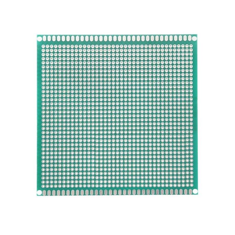
10 x 10 cm Universal PCB Prototype Board Single-Sided 2.54mm Hole Pitch
Perfect single-sided perfboard for soldering your DC power supply circuit. Standard 2.54mm pitch fits all through-hole components used in this project.

0.1µF Ceramic Capacitor (Pack of 50)
Essential bypass capacitors to place on the input and output pins of the LM7805 for stability and noise suppression in your power supply circuit.
Circuit Design: Step by Step
Here is the complete circuit flow for a 5V regulated DC power supply:
Step 1 – Transformer
Use a 230V AC primary to 9V AC secondary transformer rated at 1A. The 9V AC output after rectification and filtering gives you roughly 12V DC (peak minus diode drops). That leaves enough headroom for the LM7805 to regulate down to 5V. Avoid using a 6V transformer — the filtered output will be too close to 7V for the regulator to work correctly under load.
Step 2 – Bridge Rectifier
Connect four 1N4007 diodes in a bridge configuration, or use a single DB107 bridge rectifier module. The AC input goes to the two AC terminals; the positive and negative DC terminals come from the remaining two. Each diode drops about 0.7V, so the rectified output is approximately: 9V × √2 − 1.4V ≈ 11.3V peak.
Step 3 – Filter Capacitor
A 1000µF 25V electrolytic capacitor across the DC output of the bridge rectifier smooths the ripple. The larger the capacitor, the smoother the DC. For a 1A supply, 1000µF is adequate; for 2A, go to 2200µF. Always observe polarity — the longer lead goes to the positive rail.
Step 4 – LM7805 Voltage Regulator
Wire the LM7805 as follows:
- Pin 1 (IN): Filtered DC positive (from capacitor)
- Pin 2 (GND): Common ground
- Pin 3 (OUT): Regulated 5V output
Place a 0.33µF ceramic capacitor between Pin 1 and GND, and a 0.1µF ceramic capacitor between Pin 3 and GND. These suppress high-frequency oscillations. The datasheet recommends this for stable operation.
Step 5 – Power Indicator LED
Connect a 5mm LED in series with a 470Ω resistor from the 5V output to GND. This draws only about 10mA and gives you a satisfying visual confirmation that your supply is live.
Build Guide: Soldering and Assembly
Once you’ve tested the circuit on a breadboard using jumper wires and confirmed it works, move to a perfboard for a permanent build.
- Plan layout: Sketch component placement. Keep the transformer secondary wires away from the regulator output to avoid interference.
- Solder diodes first: Low-profile components go in first. Bend 1N4007 leads into the bridge configuration and solder neatly.
- Add capacitors: Mind polarity. The 1000µF cap sits closest to the bridge output.
- Mount the LM7805: If you expect more than 500mA, bolt a heatsink to it before soldering. Use thermal paste if available.
- Add indicator LED and resistor.
- Solder output terminals: Use screw-terminal blocks for easy connections to your load.

10CM Female To Female Breadboard Jumper Wires 2.54MM – 40Pcs
Use these to quickly prototype your power supply circuit on a breadboard before committing to a permanent soldered build. Colour-coded for easy wiring.
Testing and Troubleshooting
Before connecting your power supply to any expensive component, verify it carefully:
- No-load test: Plug in. Measure output with a multimeter. Should read 5.0V ±0.1V.
- Load test: Connect a 10Ω 5W resistor as a dummy load (0.5A draw). Output should hold at 5V.
- Ripple test: Use an oscilloscope on AC mode across the output. Ripple should be below 50mV.
Common Issues and Fixes
| Problem | Likely Cause | Fix |
|---|---|---|
| Output is 0V | Blown fuse or reversed bridge diode | Check fuse and diode orientation |
| Output is ~11V (not regulated) | LM7805 not connected properly | Recheck pinout (face flat side toward you) |
| LM7805 gets very hot quickly | No heatsink under high load | Attach aluminium heatsink |
| High ripple on output | Filter capacitor too small or ESR high | Use 2200µF or add a second 1000µF in parallel |
Useful Upgrades and Variations
Once your basic 5V supply is working, consider these upgrades:
Use an SMPS Module Instead
Switched-mode power supply (SMPS) modules are far more efficient than linear regulators. They don’t waste power as heat. For example, a 12V 10A SMPS metal module can power an entire project bench. You can pair it with a DC-DC buck converter to get adjustable 5V output with high efficiency.
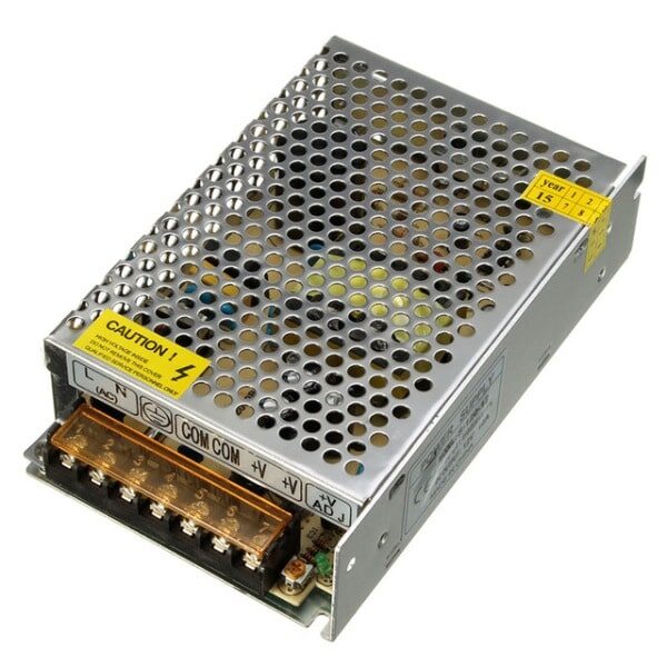
12V 10A SMPS – 120W – DC Metal Power Supply
A high-quality 120W metal SMPS that directly converts 230V AC to 12V DC. Pair with a buck converter to get any voltage from 1.2V to 12V at high efficiency.
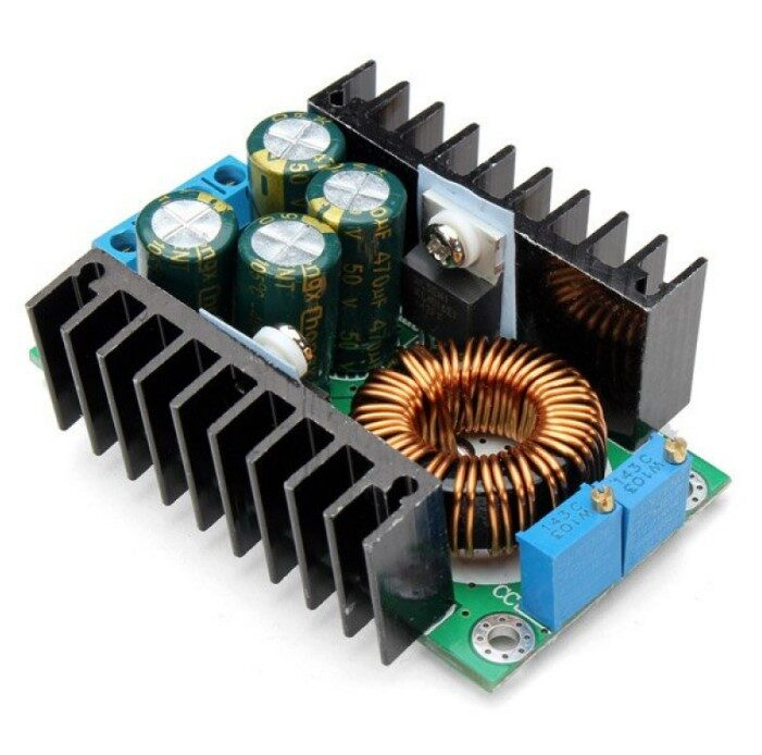
300W 10A DC-DC Step-down Buck Converter Adjustable Constant Voltage Module
An efficient adjustable buck converter that pairs perfectly with any 12V SMPS. Dial in exactly 5V, 3.3V, or any output voltage you need with constant voltage and current control.
Add a Voltmeter and Ammeter Display
A small digital voltmeter/ammeter panel (VA meter) added to the output terminals turns your supply into a professional-looking bench instrument. These cost under ₹100 and are powered directly from the 5V output.
Multiple Output Voltages
Use LM7812 and LM7805 together (or a single adjustable LM317) to have both 12V and 5V outputs from a single transformer. Ideal for projects that need both logic-level and motor-driving voltages.
Frequently Asked Questions
Q: Can I use this power supply to power an Arduino?
Yes. A regulated 5V output from this circuit can power an Arduino Uno or Nano directly via the 5V pin (bypassing the onboard regulator). Ensure your supply can deliver at least 500mA, and always include a fuse for protection.
Q: Why does the LM7805 get hot?
The LM7805 is a linear regulator, meaning it dissipates the difference between input and output voltage as heat. For example, with a 12V input and 5V output at 1A, it dissipates 7W as heat. Always attach a heatsink for loads above 300mA and consider switching to an SMPS-based design for efficiency above 500mA.
Q: What is the maximum current I can draw from an LM7805?
The LM7805 can deliver up to 1.5A with an adequate heatsink. For higher currents (2A+), use an LM338 or a dedicated SMPS module with a buck converter instead.
Q: Can I build a variable output power supply with this design?
Yes. Replace the LM7805 with an LM317 adjustable voltage regulator. Using a potentiometer in the adjustment pin resistor divider, you can vary the output from 1.25V to about 25V (depending on input voltage). The formula is Vout = 1.25 × (1 + R2/R1).
Q: Is it safe to build this if I’m a beginner?
The mains-connected transformer secondary is safe once isolated. Never touch the primary side (230V). Always use a fuse on the primary, work with the power disconnected during soldering, and test with a multimeter before connecting to any sensitive electronics.
Ready to Start Building?
Get all the components you need — from resistors and capacitors to SMPS modules and buck converters — at Zbotic.in. We stock genuine components with fast delivery across India. Build your power supply today and take your electronics projects to the next level!


Add comment