
Every electronics project starts on a breadboard, and the quality of your breadboard power supply determines the reliability of everything built on top of it. A shaky or noisy power rail is the hidden cause behind the majority of frustrating debugging sessions — where the circuit looks correct on paper but refuses to work consistently in real life. Getting your 3.3V and 5V rails clean, stable, and properly decoupled is one of the highest-ROI skills a maker can develop.
In this step-by-step guide we explain how to set up a solid dual-rail (3.3V and 5V) breadboard power supply, covering everything from the components you need to the wiring method, common pitfalls, and safety tips that keep your components alive. All components mentioned are readily available in India.
Table of Contents
- Why You Need a Dedicated Breadboard Power Supply
- Power Supply Options: USB, SMPS, Buck Converter
- Components Required
- Setting Up the 5V Rail
- Setting Up the 3.3V Rail
- Decoupling Capacitors: Why They Are Non-Negotiable
- Dual-Rail Setup: 3.3V and 5V Together
- Safety Tips and Common Mistakes
- Frequently Asked Questions
Why You Need a Dedicated Breadboard Power Supply
Many beginners power their breadboard directly from an Arduino’s 5V and 3.3V pins. This works for simple LED and sensor experiments, but it has serious limitations:
- Arduino’s onboard 3.3V regulator (usually an LP2985) is rated for only 50–150mA. Add a WiFi module or a display and you will immediately exceed this limit.
- The Arduino’s USB-sourced 5V shares the same rail as the USB host computer. Ground loops and noise from the USB cable can corrupt sensitive sensor readings.
- There is no current protection. A short circuit on your breadboard can damage the Arduino’s voltage regulator — or worse, the microcontroller itself.
A proper external breadboard power supply solves all these problems: it provides clean, regulated voltage with adequate current capacity, independent of your microcontroller.
Power Supply Options: USB, SMPS, Buck Converter
There are three common ways to power a breadboard in the Indian maker context:
Option 1: Dedicated Breadboard Power Supply Module (MB102 type)
These are the small blue PCB modules that plug directly into the power rails of a standard 830-point breadboard. They accept 6.5V–12V DC input (or USB) and output switchable 3.3V/5V on each rail independently. Cost: ₹50–₹150. Best for beginners and quick experiments.
Option 2: SMPS (Switching Mode Power Supply)
A mains-connected SMPS (like a 12V 2A or 12V 10A unit) provides stable DC output with high current capacity. You then use a buck converter module to step down to 5V or 3.3V on the breadboard. This combination gives you clean, high-current power suitable for motors, multiple modules, or power-hungry RF components. Cost: ₹300–₹900 for SMPS + ₹100–₹400 for buck converter.
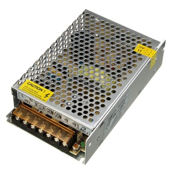
12V 10A SMPS – 120W DC Metal Power Supply
A robust 120W metal-enclosed SMPS that provides a clean 12V rail for bench work. Pair with a buck converter to get regulated 5V or 3.3V for your breadboard projects.
Option 3: Wall Adapter + Buck Converter
A 12V DC wall adapter provides a convenient, compact source that plugs into mains via an IEC connector. Combine it with a buck converter module to set whatever output voltage you need (3.3V, 5V, or any custom voltage). This is the most flexible and cost-effective approach for a permanent bench setup.
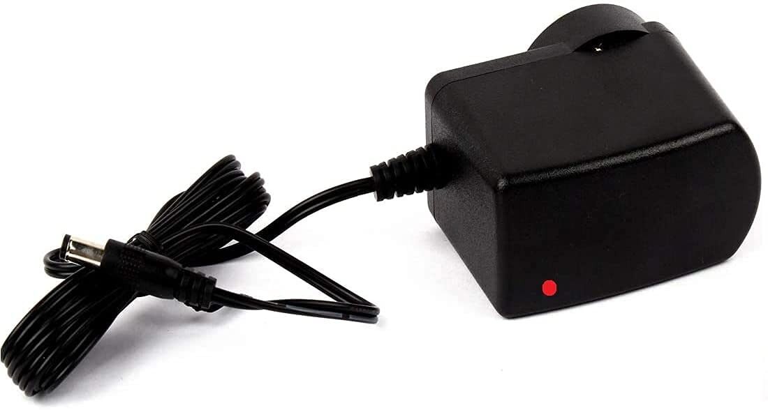
12V 2A Power Supply with 5.5mm DC Plug Adapter
A clean 12V 2A wall adapter that works as the primary input for a buck converter-based breadboard power supply. Compatible with Indian mains voltage (220V AC).
Components Required
For a dual-rail 3.3V + 5V breadboard power supply using a buck converter approach, you will need:
- 12V DC power adapter (1A or 2A) or 12V SMPS
- DC-DC buck converter module (adjustable, e.g., LM2596-based or XL4016)
- Breadboard (830-point recommended for adequate space)
- 100nF ceramic capacitors × 4 (decoupling — one per IC power pin)
- 10µF electrolytic capacitors × 2 (bulk decoupling at the power entry point)
- Jumper wires (male-to-male for the breadboard rails)
- Multimeter (to verify output voltage before connecting your circuit)
- Optional: LED + 330Ω resistor as a power-on indicator
Setting Up the 5V Rail
Follow these steps to establish a clean 5V rail on your breadboard:
- Set the buck converter output to 5V. Connect your 12V input to the buck converter’s input terminals. Use a multimeter on the output terminals while slowly adjusting the onboard potentiometer until you read exactly 5.00V. Do this before connecting anything to the output.
- Connect the output to the breadboard power rails. Run a wire from the buck converter’s positive output to the red (+) power rail of the breadboard. Run the negative output to the blue (−) rail. These two horizontal rails now carry 5V and GND respectively.
- Bridge the rail pairs if needed. Standard 830-point breadboards have two pairs of power rails (one on each long side). They are NOT internally connected. Use short jumper wires to bridge the top-left rail to the top-right rail (both + and −) if you want 5V available on both sides.
- Add a power LED indicator. Place a 330Ω resistor in series with an LED between the 5V rail and GND. This gives you an instant visual confirmation that power is live — a safety habit worth building early.
Setting Up the 3.3V Rail
The cleanest way to derive 3.3V from a 5V rail is with a dedicated linear regulator:
Method A: AMS1117-3.3 Linear Regulator
The AMS1117-3.3 is a low-dropout regulator that takes up to 5V input and outputs a clean 3.3V at up to 800mA. Wire it as follows:
- Pin 1 (GND) → GND rail
- Pin 2 (Output) → 3.3V output node
- Pin 3 (Input) → 5V rail
- Place a 10µF capacitor between the output pin and GND (as close to the IC as possible)
- Place a 100nF ceramic capacitor between the input pin and GND
This setup is used on nearly every Arduino, ESP32, and Raspberry Pi board — so understanding it makes you instantly more confident reading those boards’ schematics.
Method B: Second Buck Converter Channel
If you need more than 800mA at 3.3V (e.g., running an ESP8266 or ESP32 at full WiFi transmit power, which peaks at 500mA), use a second adjustable buck converter set to 3.3V. Set it from the 12V input directly, not from the 5V rail. This avoids loading the 5V rail and gives each rail its own independent regulation.
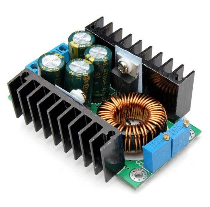
300W 10A DC-DC Step-down Buck Converter Adjustable
A high-current adjustable buck converter that you can dial to exactly 3.3V or 5V. The constant voltage and current modes make it safe for sensitive digital components.
Decoupling Capacitors: Why They Are Non-Negotiable
Even with a perfect buck converter or linear regulator, the power rails on a breadboard carry noise. Every time a digital IC switches state, it draws a brief spike of current. Without decoupling capacitors, this spike travels along the power rail and can corrupt data, cause resets, or create RF interference.
The decoupling rule: Place a 100nF ceramic capacitor between VCC and GND as close as physically possible to each IC’s power supply pins. On a breadboard this means in the row directly beside the IC’s VCC pin, bridging between the VCC pin row and the GND rail.
Additionally, place a 10µF electrolytic capacitor at the point where your supply enters the breadboard. This bulk capacitor handles slower, larger current transients that the ceramic caps cannot.
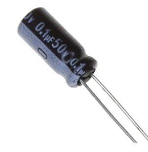
0.1µF 50V Capacitor (Pack of 50)
These 100nF 50V capacitors are the standard decoupling cap used across all digital circuits. Keep a pack on your bench — you will use them in every project you build.
Dual-Rail Setup: 3.3V and 5V Together
Many real projects need both voltage levels simultaneously — for example, an Arduino Uno (5V logic) communicating with an ESP8266 WiFi module (3.3V logic). Here is how to organise the dual-rail breadboard:
- Top power rails: 5V (red) and GND (blue) — for 5V components like Arduino, 74HC logic ICs, and 5V sensors
- Bottom power rails: 3.3V (red) and GND (blue) — for 3.3V components like ESP8266, ESP32, OLED displays, and SD card modules
- Connect both GNDs together using a jumper wire. All grounds must share a common reference — failure to do this is a common cause of mysterious communication failures between 5V and 3.3V devices.
- Never connect a 5V output to a 3.3V input directly. Use a voltage divider (two resistors) or a logic level converter module for signals crossing the voltage boundary.
Safety Tips and Common Mistakes
Always measure output voltage before connecting your circuit
Adjustable buck converters sometimes have their potentiometer pre-set at the factory in ways that give unsafe output voltages. Always use a multimeter to confirm 5.00V and 3.30V before plugging in any IC or module.
Check polarity before powering on
Reversing VCC and GND can destroy ICs, LEDs, and electrolytic capacitors instantly. Double-check every connection after wiring and before switching power on.
Use current-limiting buck converters
Adjustable buck converters with CC (constant current) mode let you set a maximum current limit. This is valuable protection when debugging — if your circuit accidentally shorts, the supply limits current rather than allowing the short to burn components.
Keep power rails short
Long jumper wires on the power rail add inductance and resistance, making the supply less clean. Keep power distribution wires as short as practical, especially near high-frequency switching components.
Frequently Asked Questions
Can I use a USB phone charger as a breadboard power supply?
Yes, a 5V USB charger works for low-current circuits (sensors, small displays, a few LEDs). For anything drawing over 500mA — such as motors, high-power LEDs, or multiple WiFi modules — use a proper DC adapter or SMPS with a buck converter. USB chargers also tend to be noisier than regulated bench supplies.
What is the difference between a linear regulator and a buck converter for breadboard power?
A linear regulator (like AMS1117 or 7805) is simple and produces very clean output but wastes excess voltage as heat. A buck converter is more efficient but generates some switching noise. For sensitive analog circuits, use a linear regulator or add extra filtering after a buck converter. For digital circuits, a buck converter is usually fine with proper decoupling caps.
How much current can a standard breadboard handle?
The internal copper strips of a standard breadboard are typically rated for 1A. Exceeding this can cause heat buildup and eventual failure. For high-current loads (motors, high-power LEDs), run the heavy current directly from your supply to the load, bypassing the breadboard rails entirely.
Do I need a separate GND for 3.3V and 5V sections?
No — both sections should share the same GND. Separate, unconnected grounds create a floating reference that causes communication errors between devices on different rails. Always connect all ground rails together at one common point.
Can I run ESP32 or ESP8266 directly from a breadboard power supply module?
Yes, provided the module’s 3.3V rail can supply at least 500mA continuously (some cheap modules cap out at 300mA). The ESP8266 can draw up to 300–400mA during WiFi transmission and the ESP32 up to 500mA. Use a buck converter rated for at least 1A on the 3.3V rail if you are running these modules.
Power Your Next Project the Right Way
A clean, well-designed breadboard power supply is the foundation that makes every other part of your project more reliable. Getting your 3.3V and 5V rails right means less debugging time, fewer mysterious resets, and components that survive longer.
Zbotic stocks all the components you need to build a professional-grade bench power setup — SMPS units, buck converters, decoupling capacitors, and jumper wires — delivered quickly across India. Head to our Electronics Basics store to pick up your power supply components today and take your prototyping to the next level.


Add comment